![]()
![]()
|
|
|
|
Richard's 1972 Porsche 914 BlogThis Blog is my online documentation of my progress on my 914. While most of my other pages show the order from oldest to newest top to bottom. I will do this page Blog style in newest to oldest top to bottom. ArchiveLinks below are archived entries from past years.
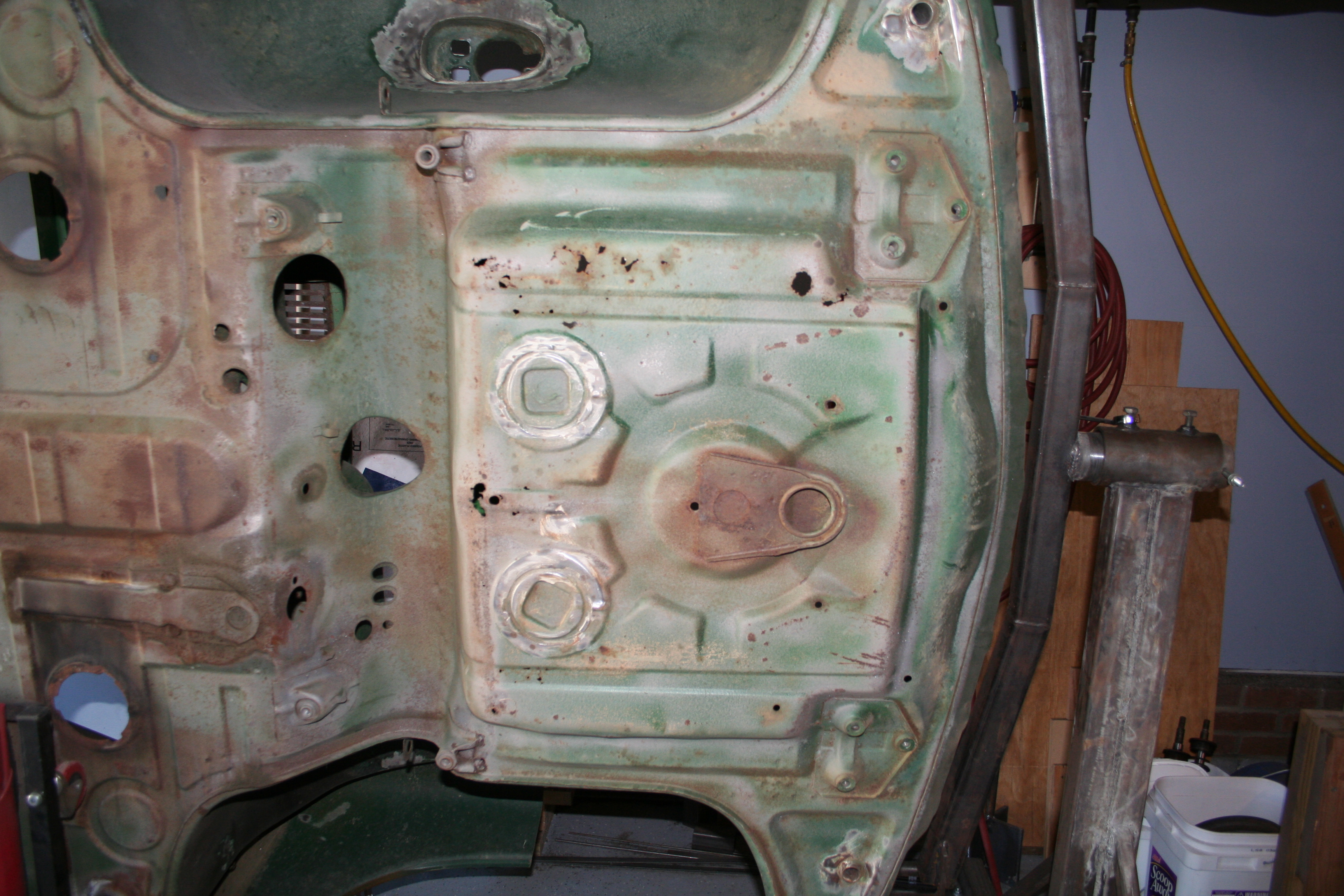
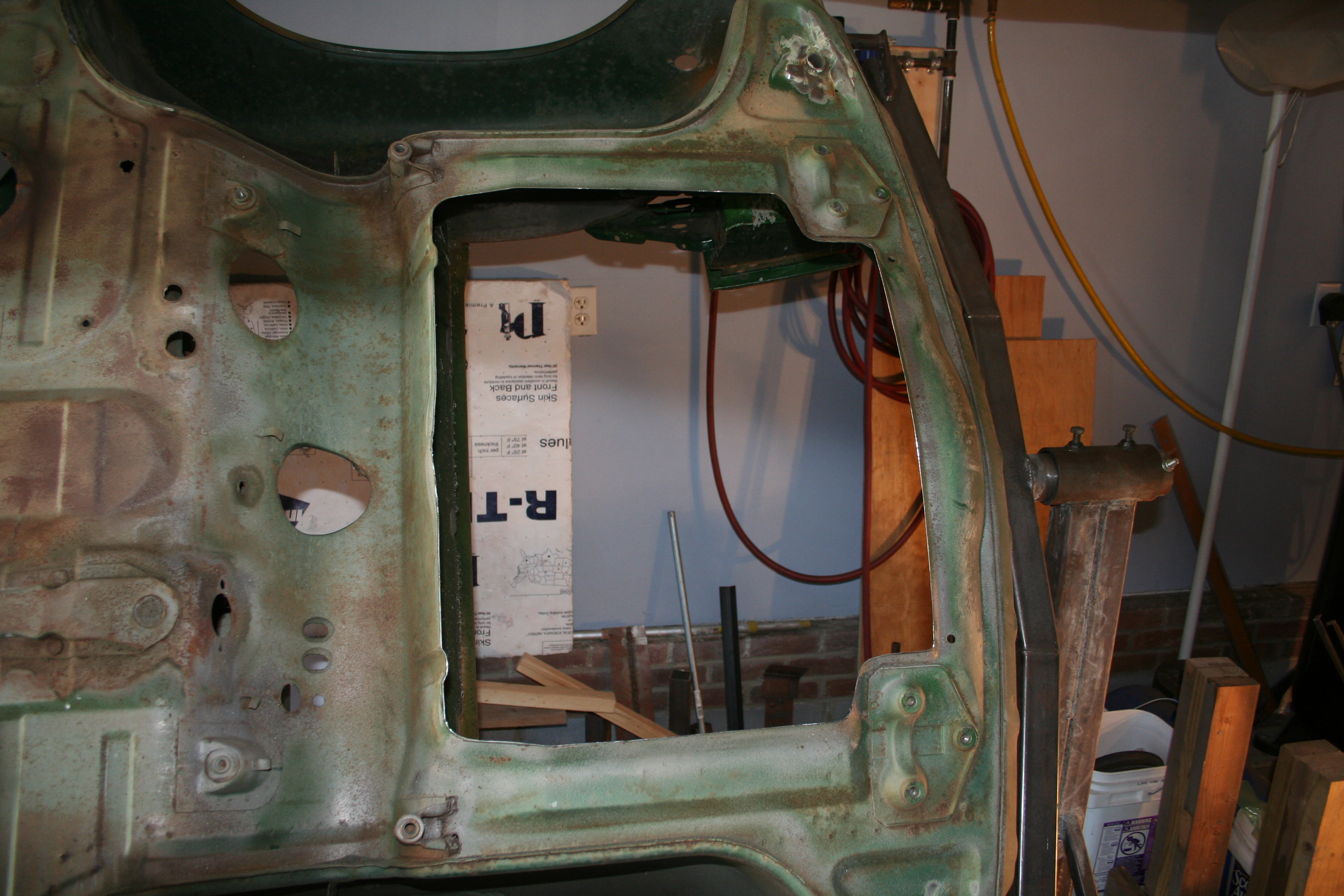
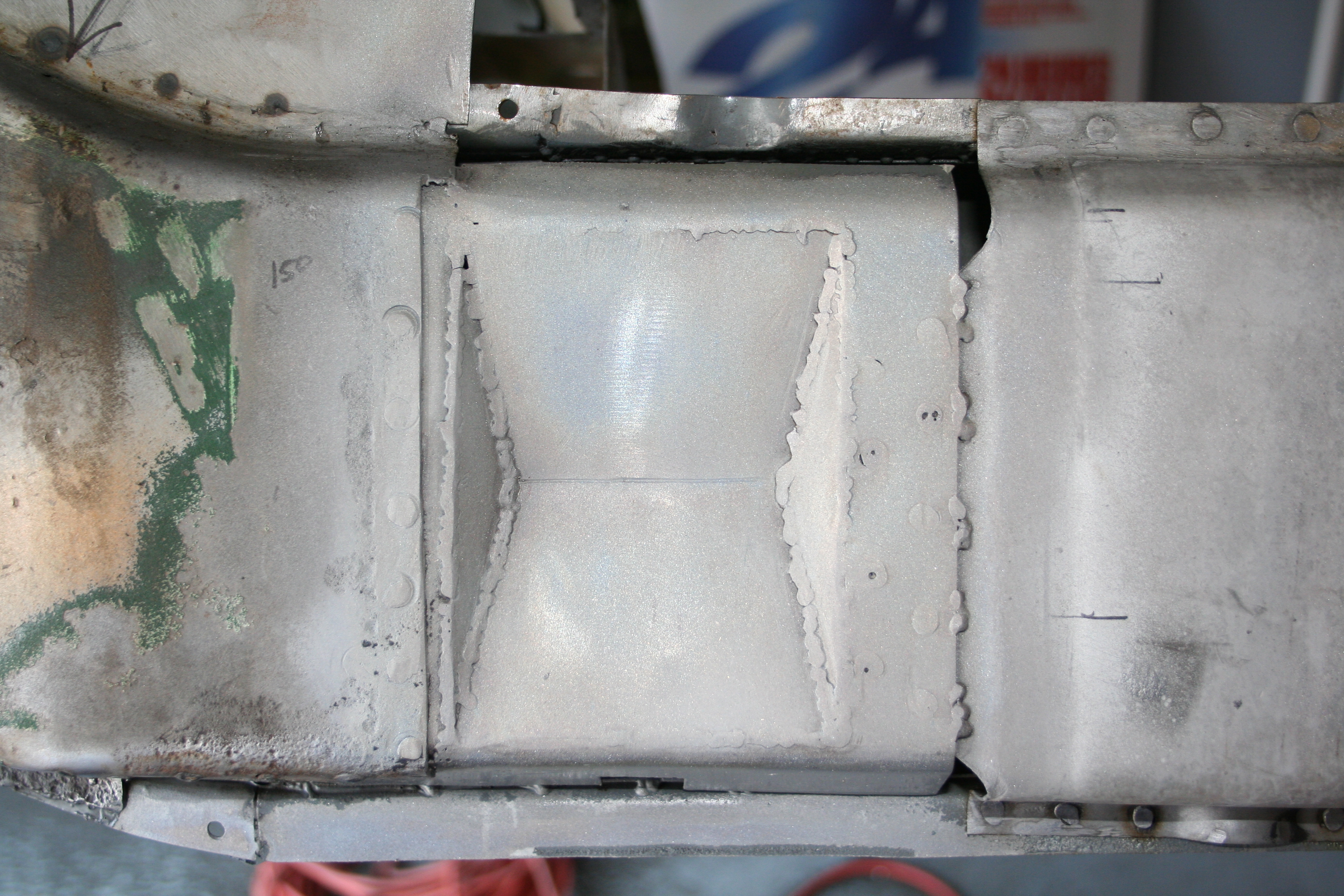
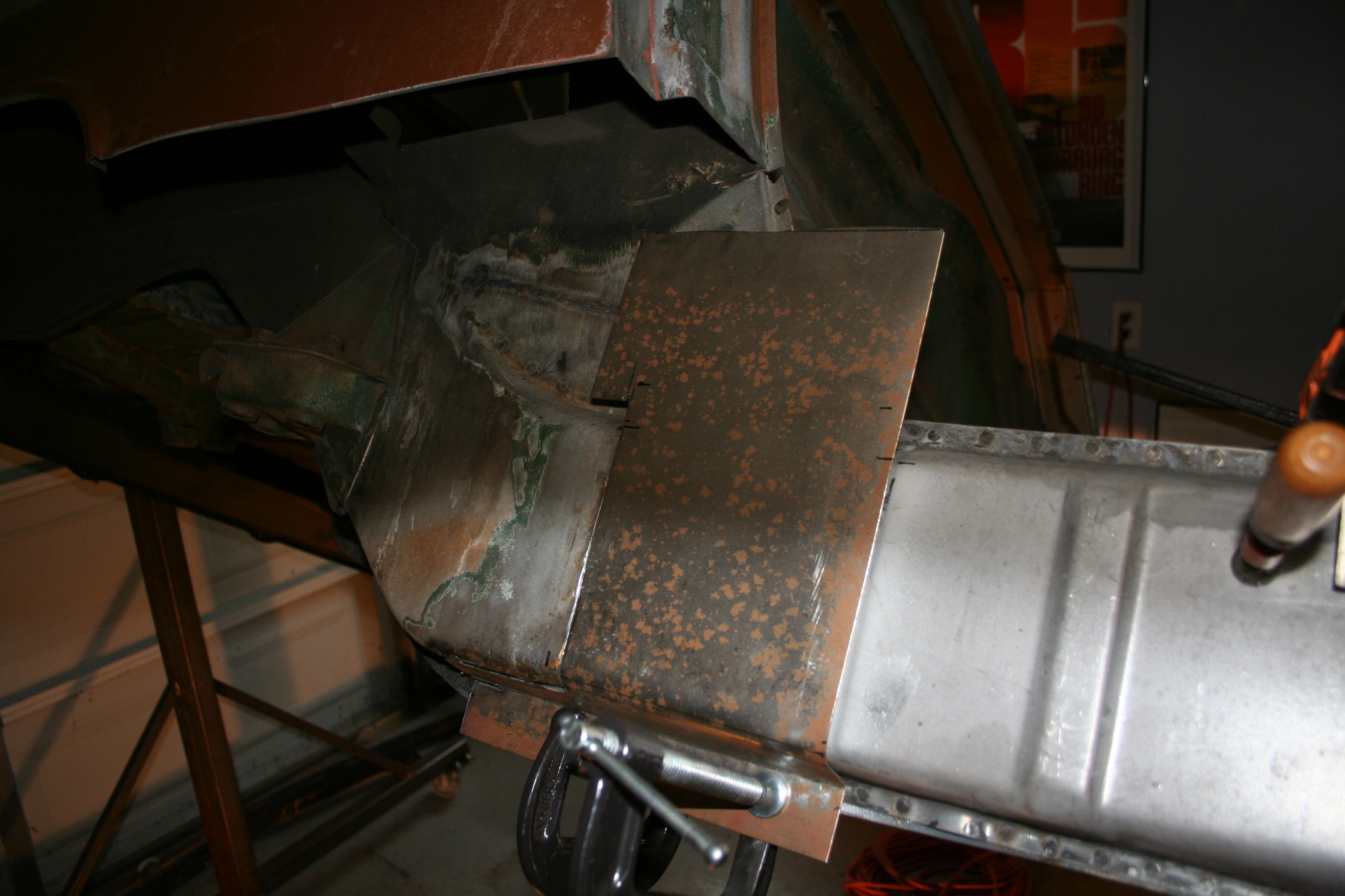
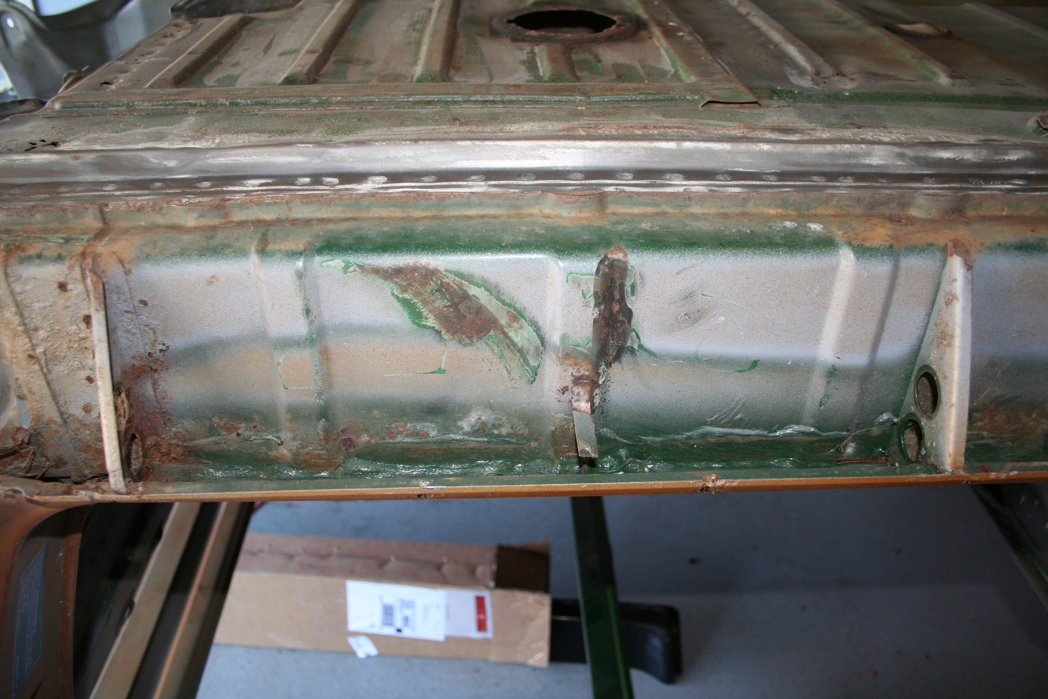
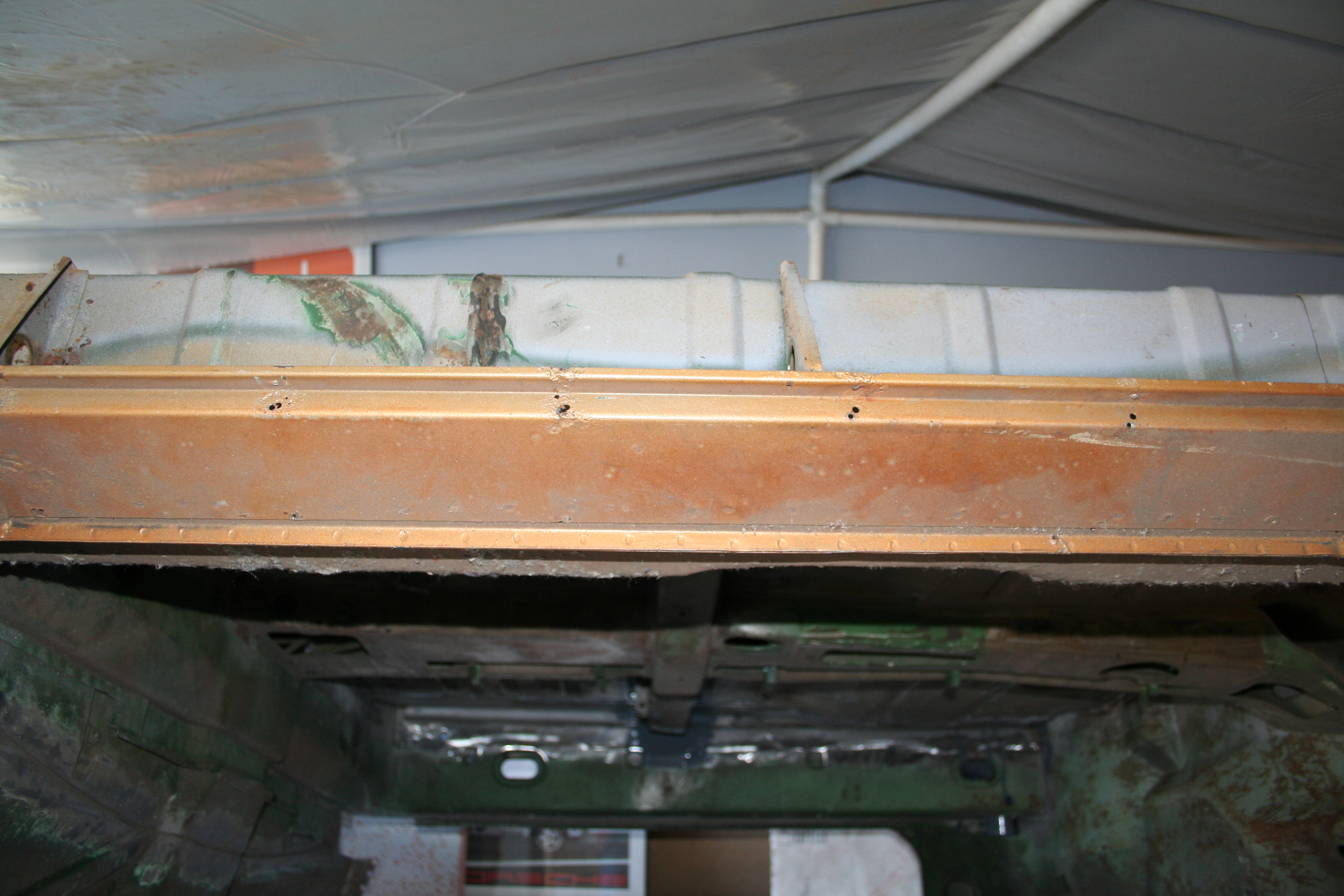
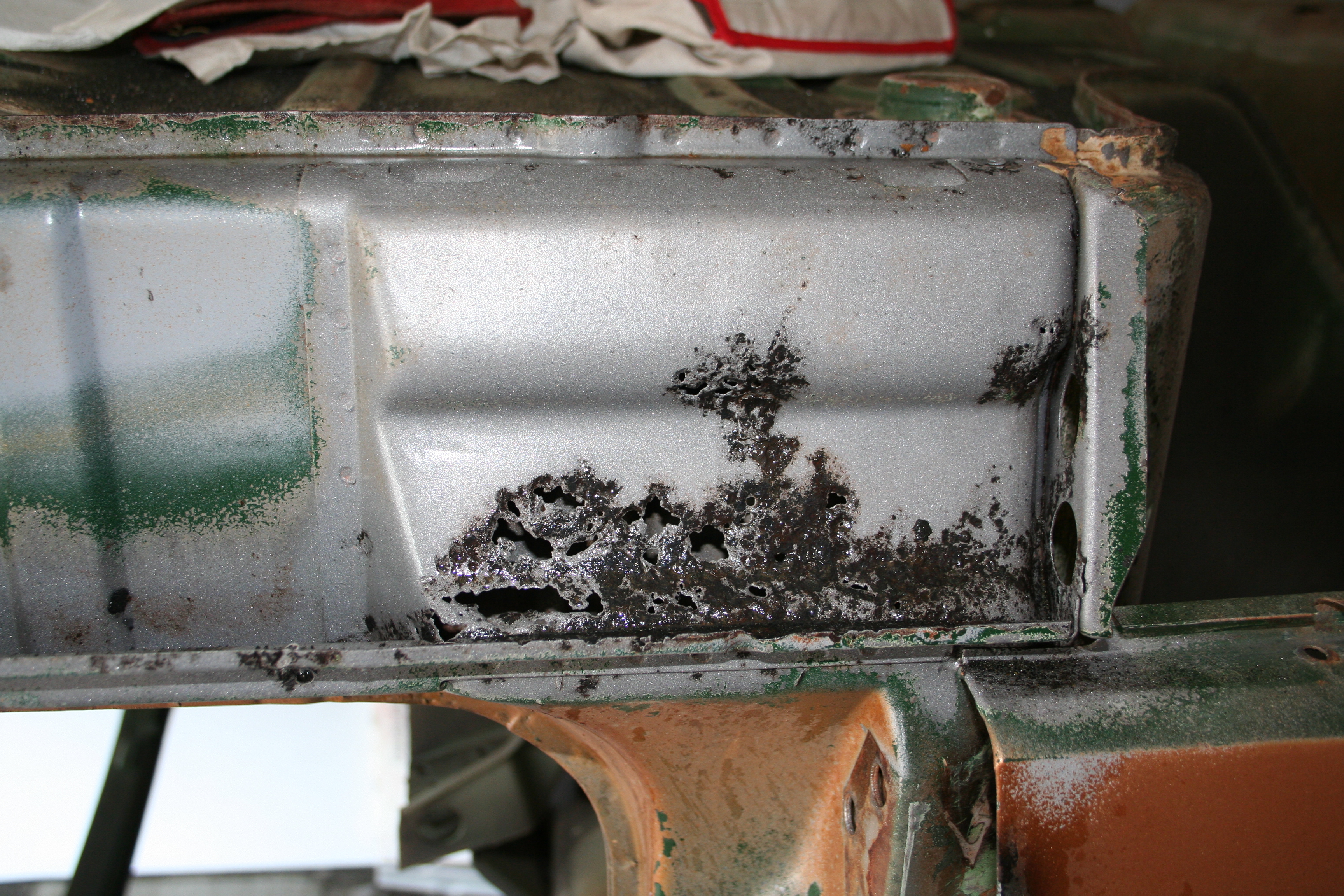
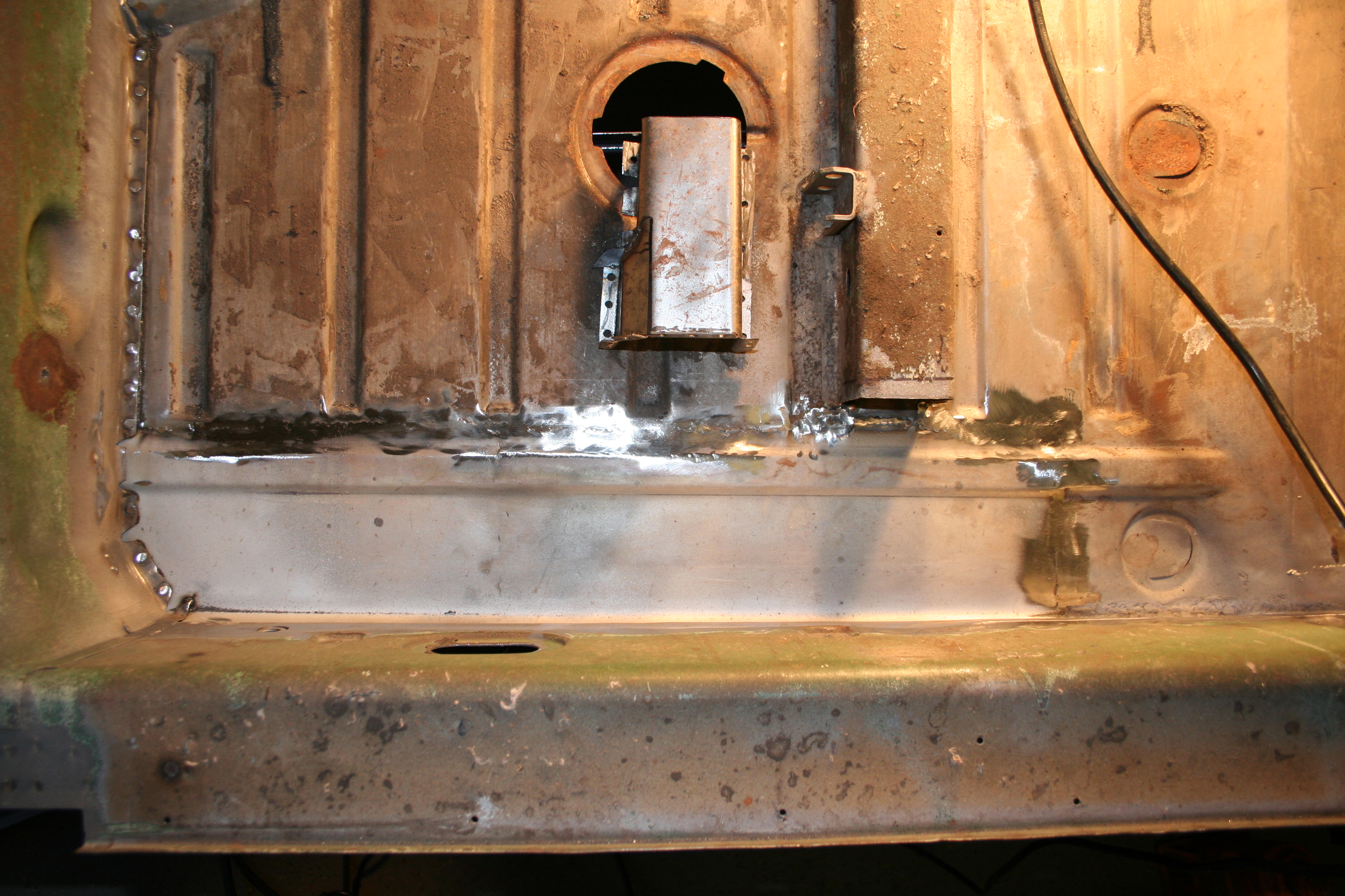
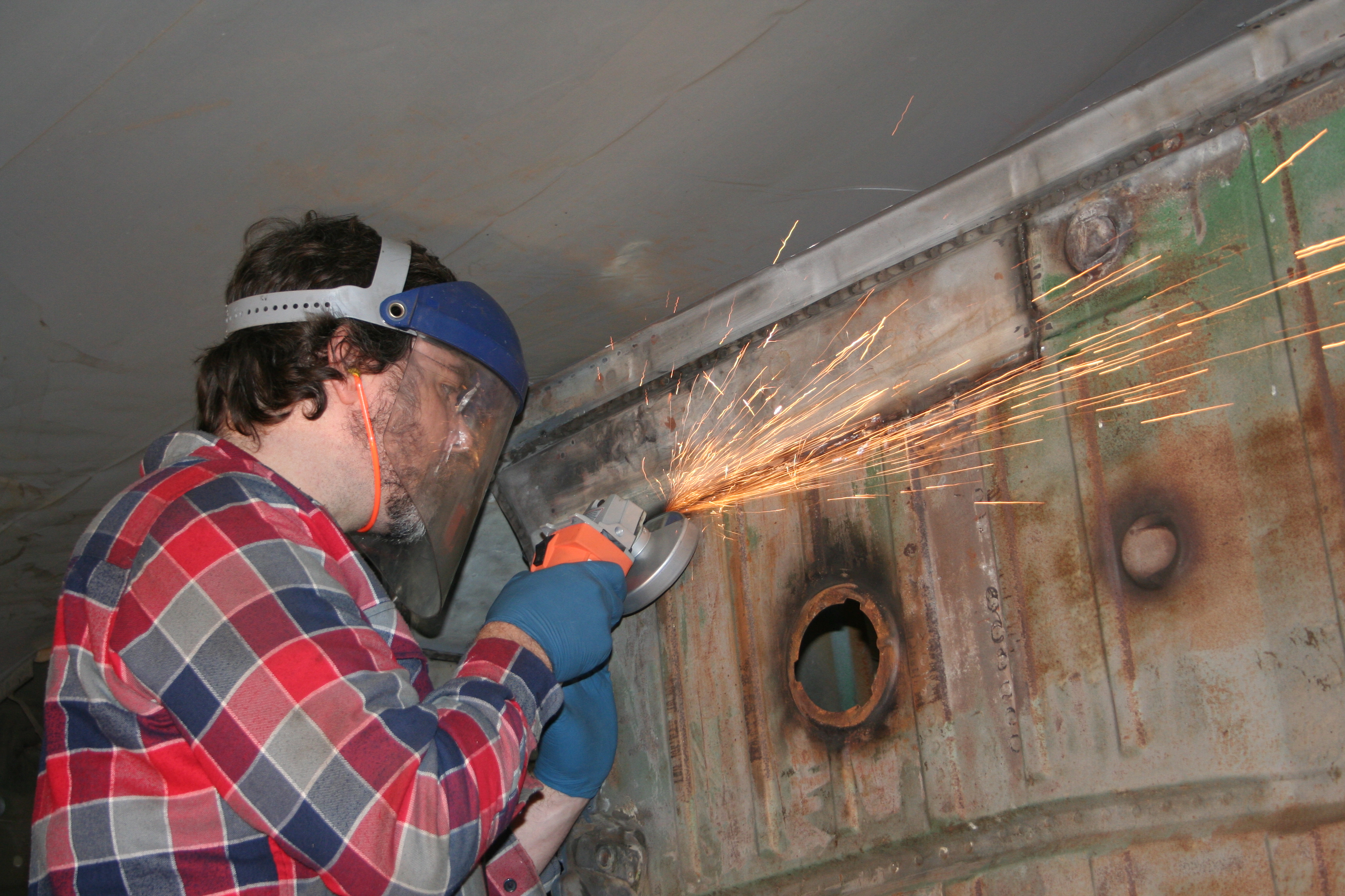
Current5/30 - 6/1/2009I have been working on rebuilding brake calipers at night and (noisy) body work during the day. I have generally been tired of working on the longitudinals recently, so I decided to take a break and work on replacing the front trunk. I bought a replacement front trunk from someone months ago (can't remember who at this point) and will be cutting out the old and welding in the new. This is a common repair for the 914 for two reasons. First if your car had A/C installed, the dealer would have cut a big hole in the front trunk to install the condenser coil. If you remove the A/C you need to fix that hole. The second is that it's a common place for pin hole rust spots to develop.
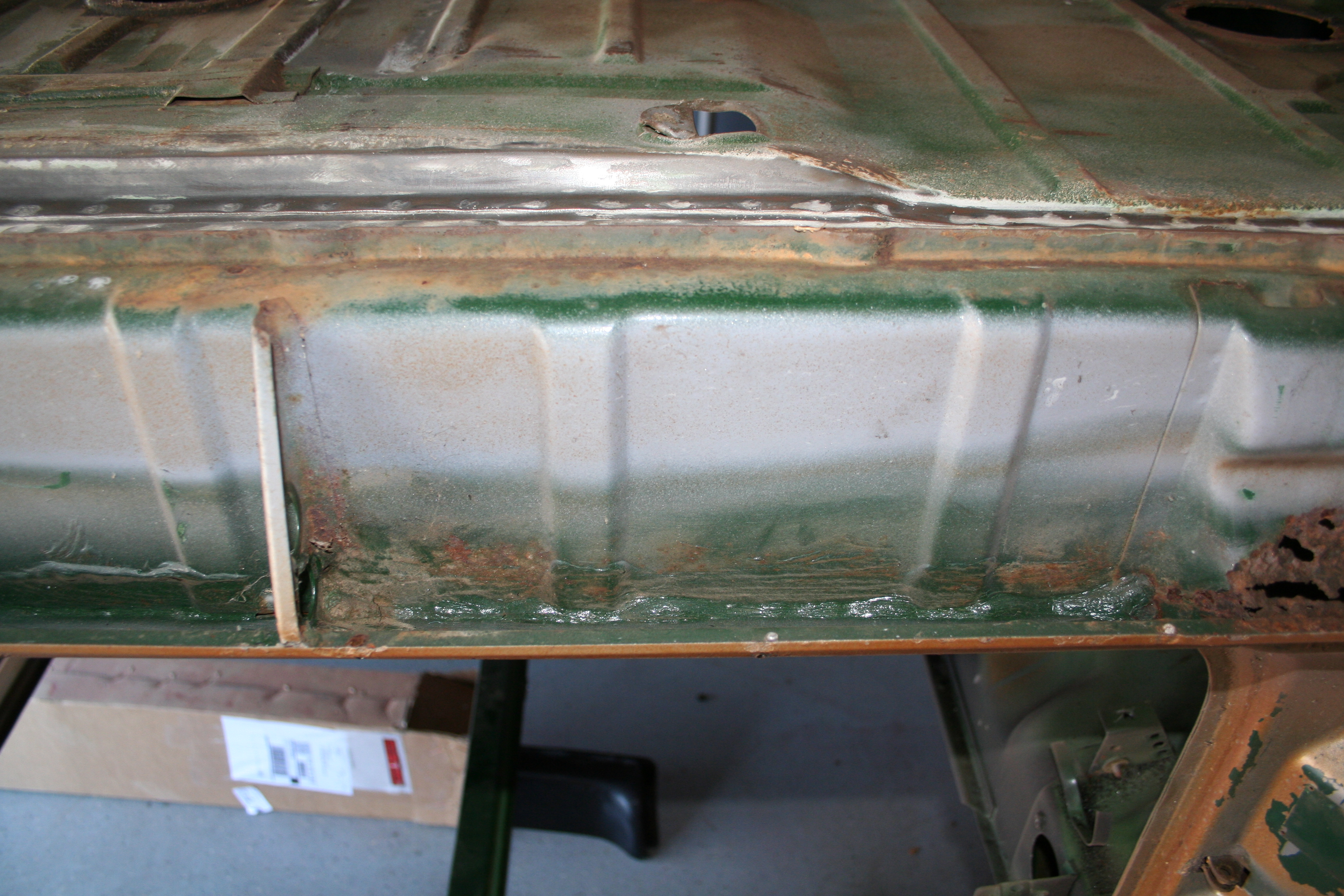
Here is the bottom view. You can see some of the rust.
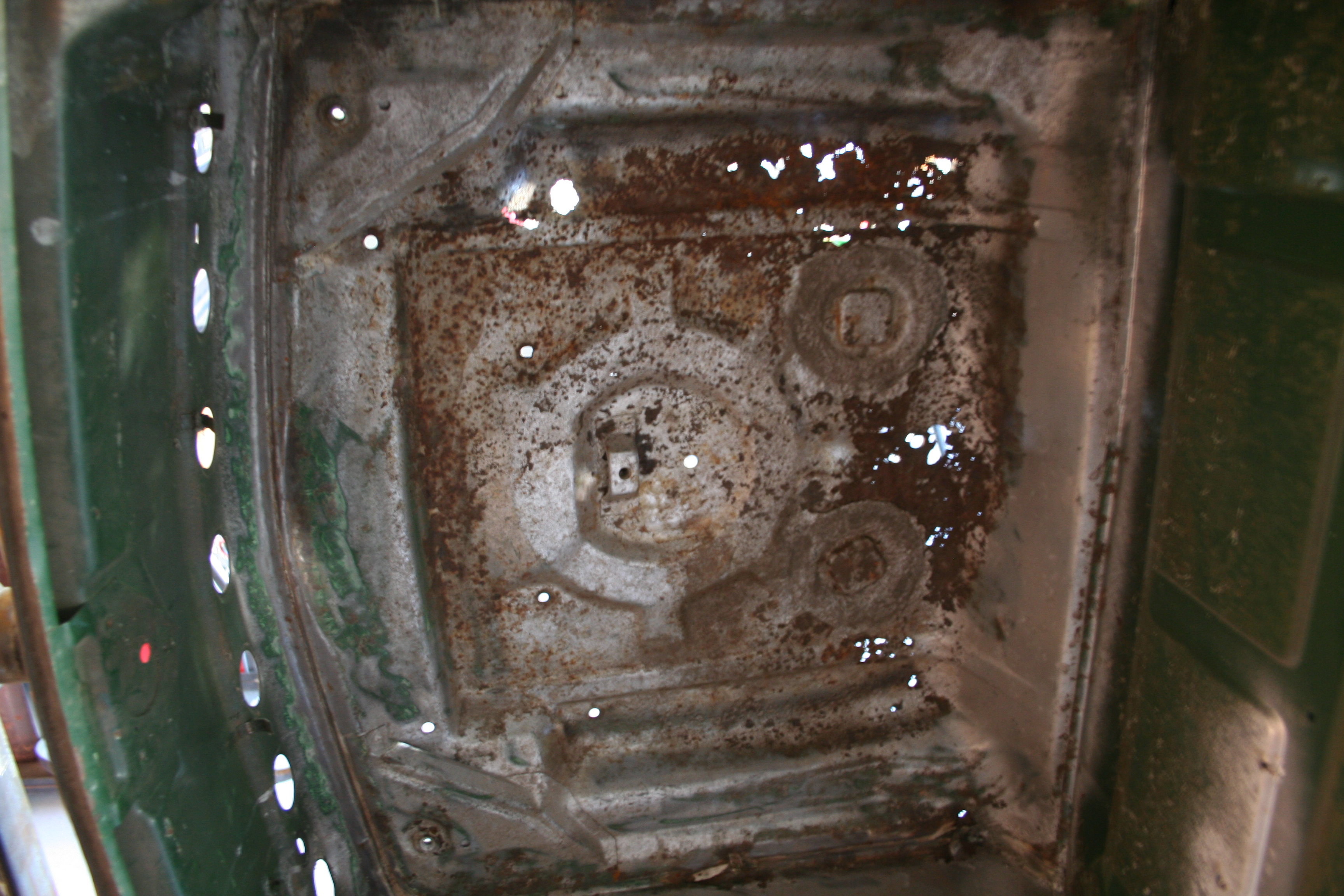
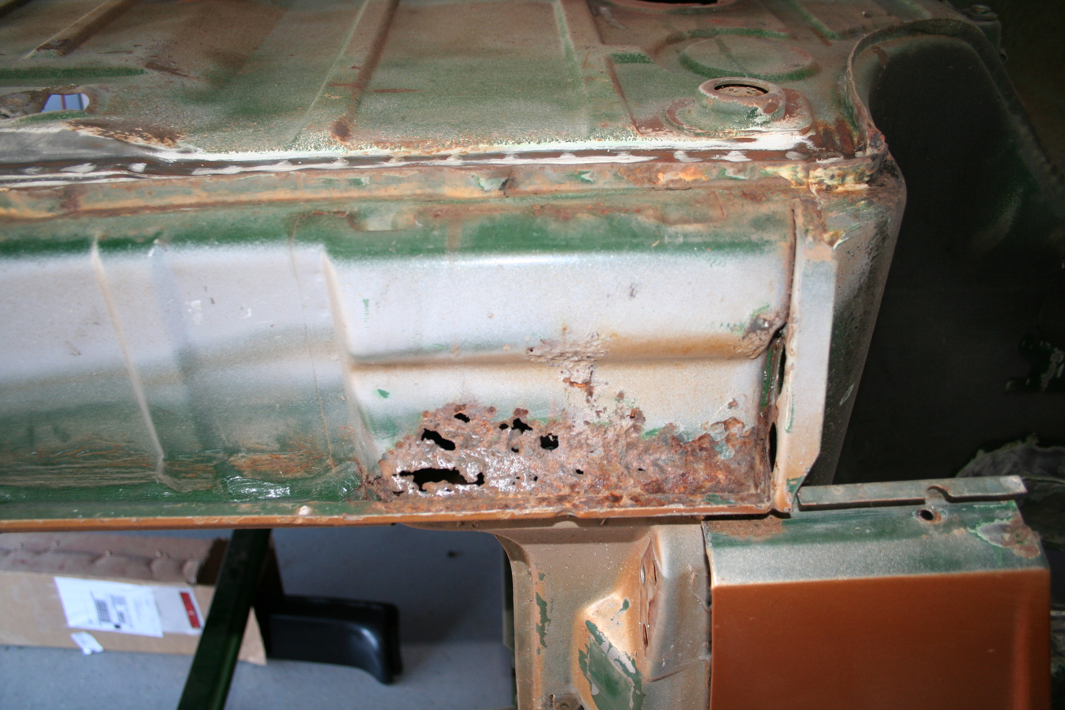
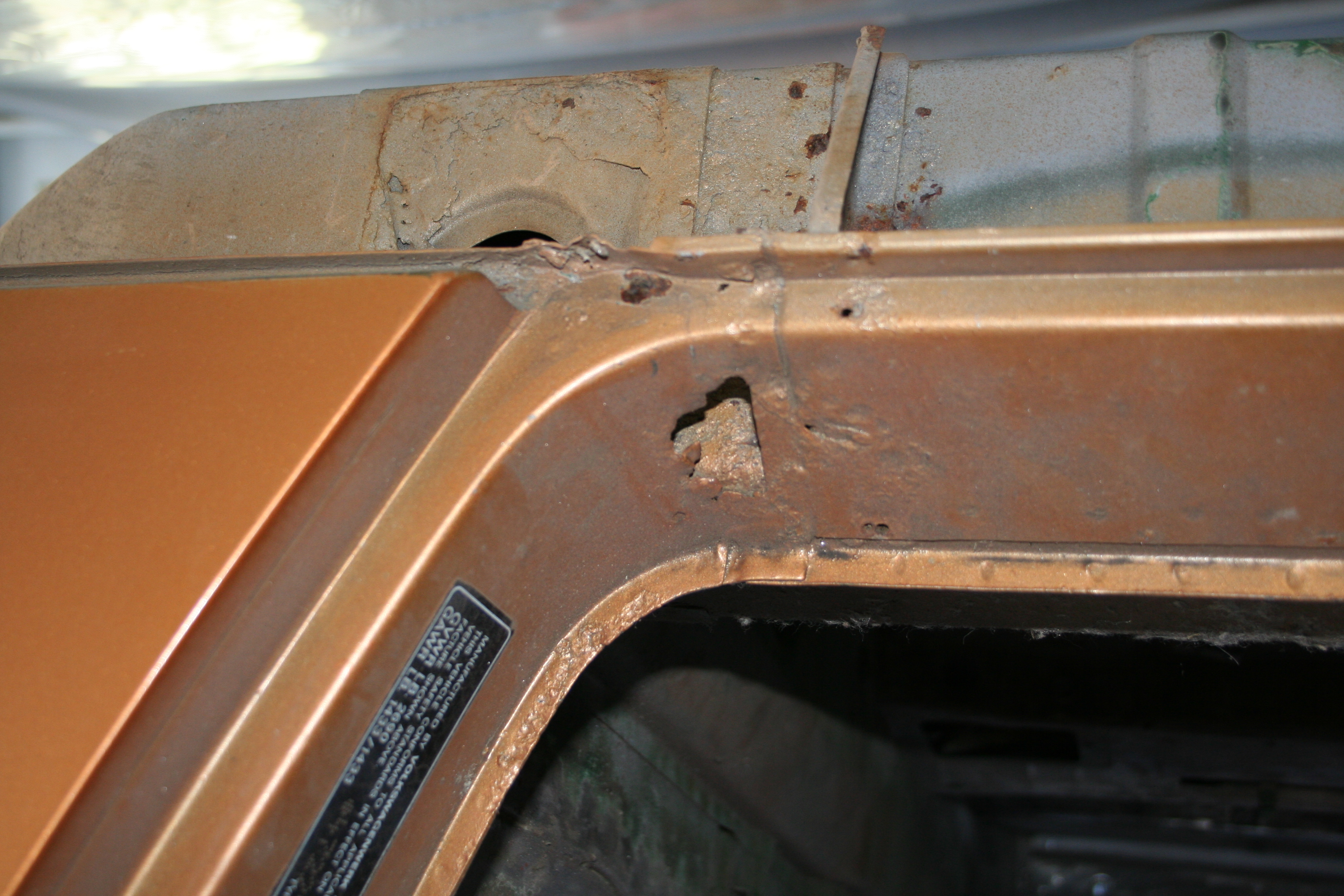
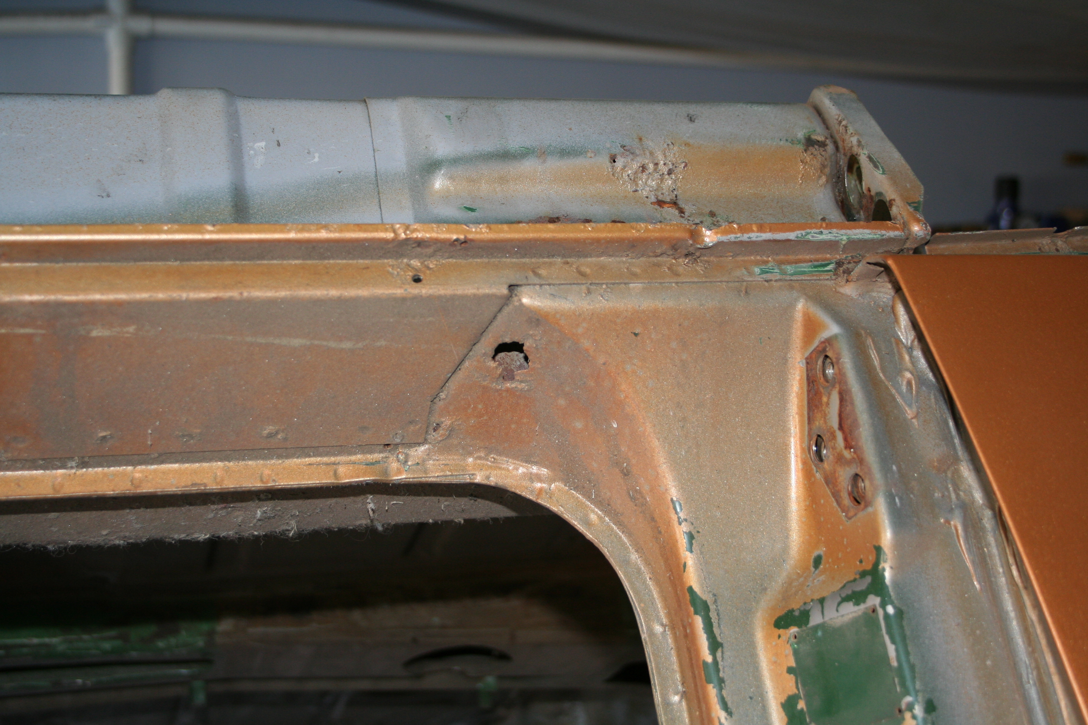
Shot from the inside with no flash. You can see the Swiss cheese nature of my front trunk.
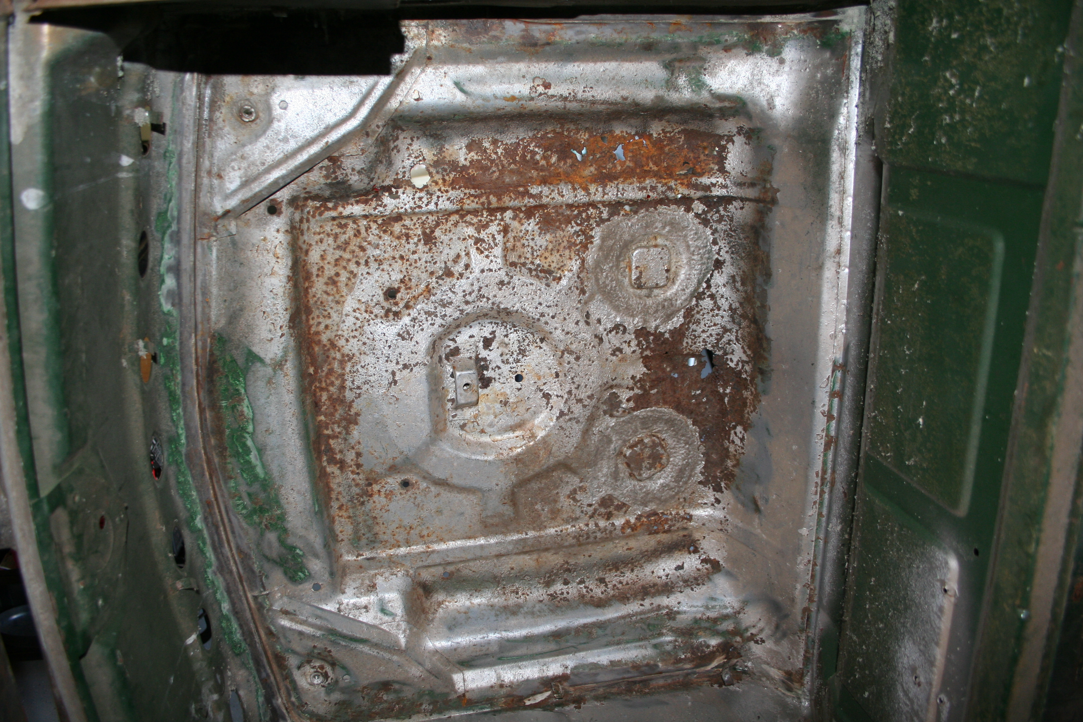
Shot from the inside with flash.
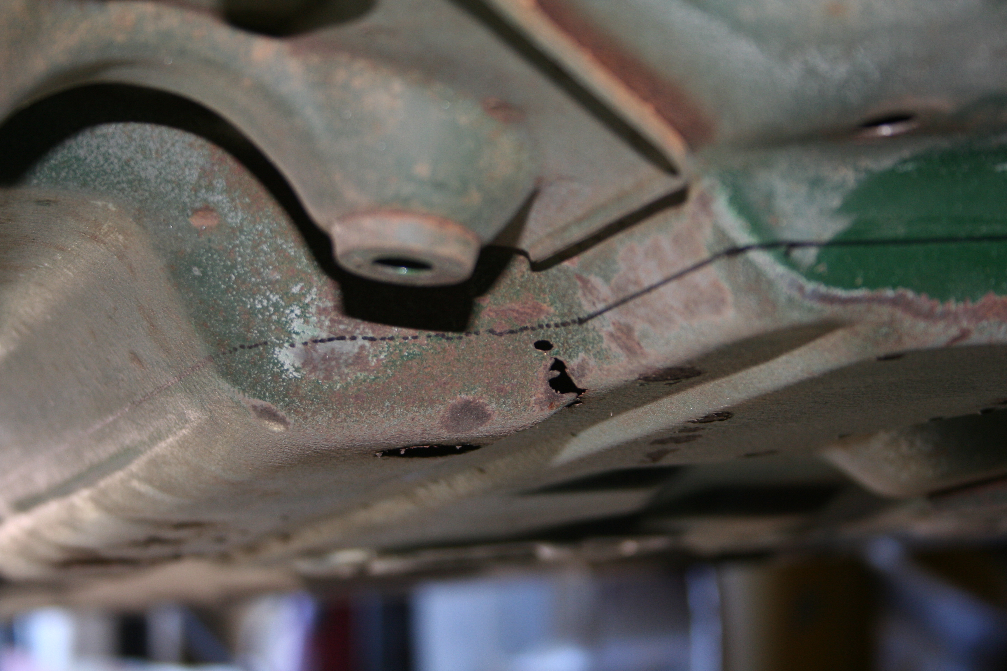
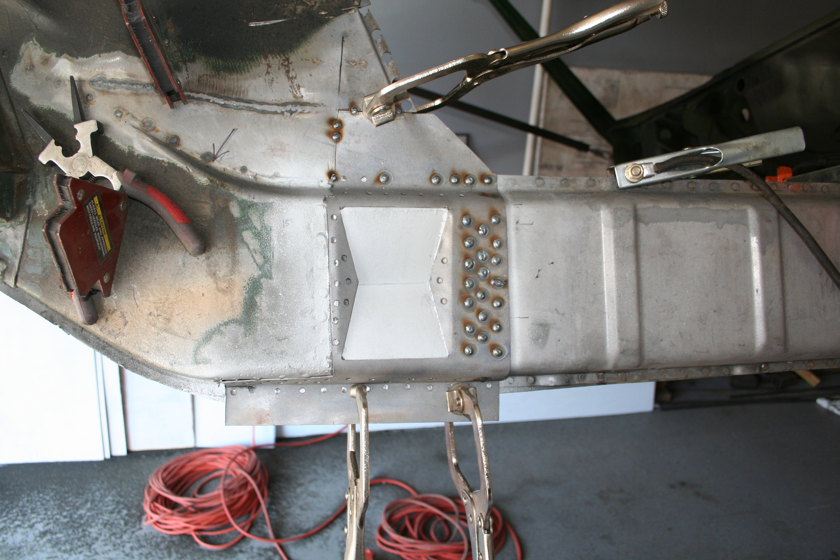
I marked around the perimeter and tried to mark on a flat surface as much as possible. I also am trying to make the cut in a flat "plane" so it will hopefully make it easier to fit the replacement.
More cut marks around the perimeter
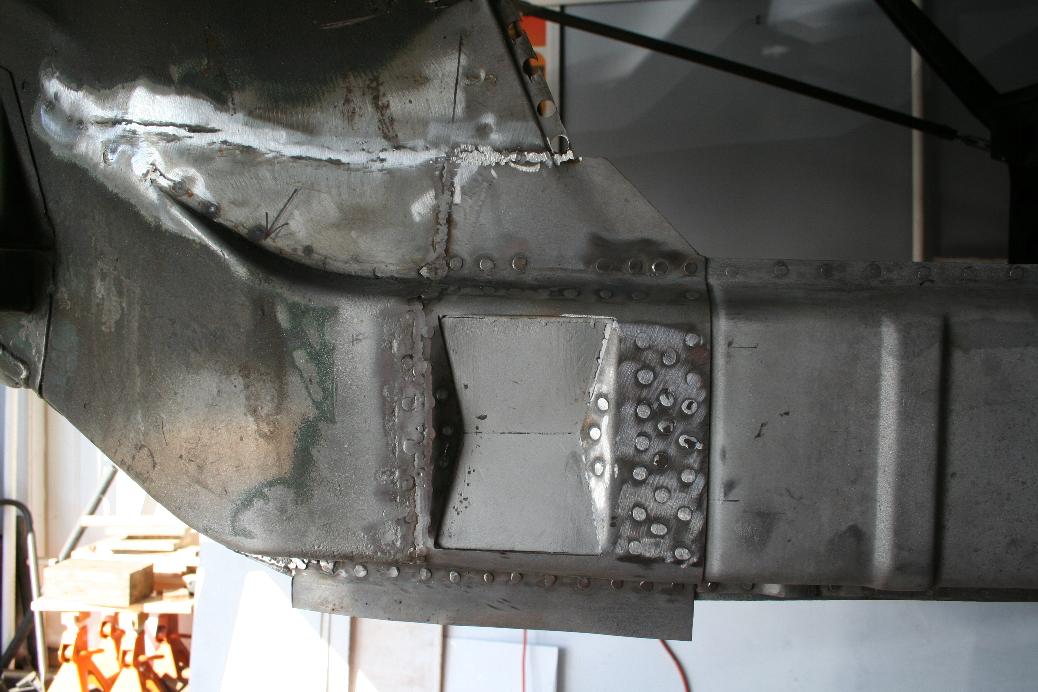
I used an angle grinder with a thin cutting wheel. I think a reciprocating saw would also work, but in my opinion it's easier to cut straight lines with the angle grinder.
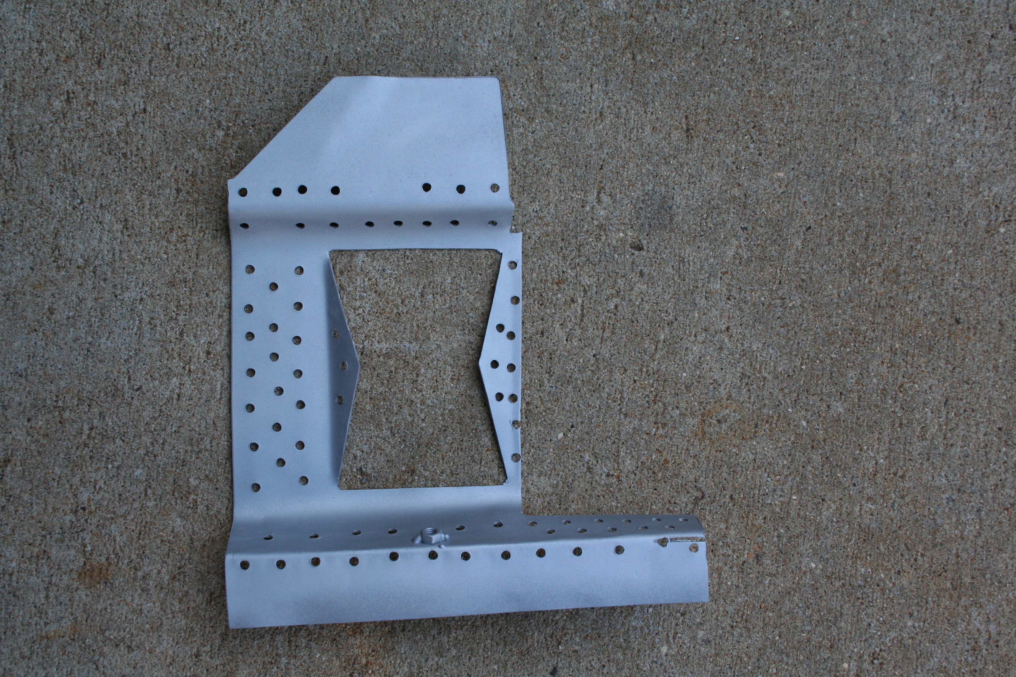
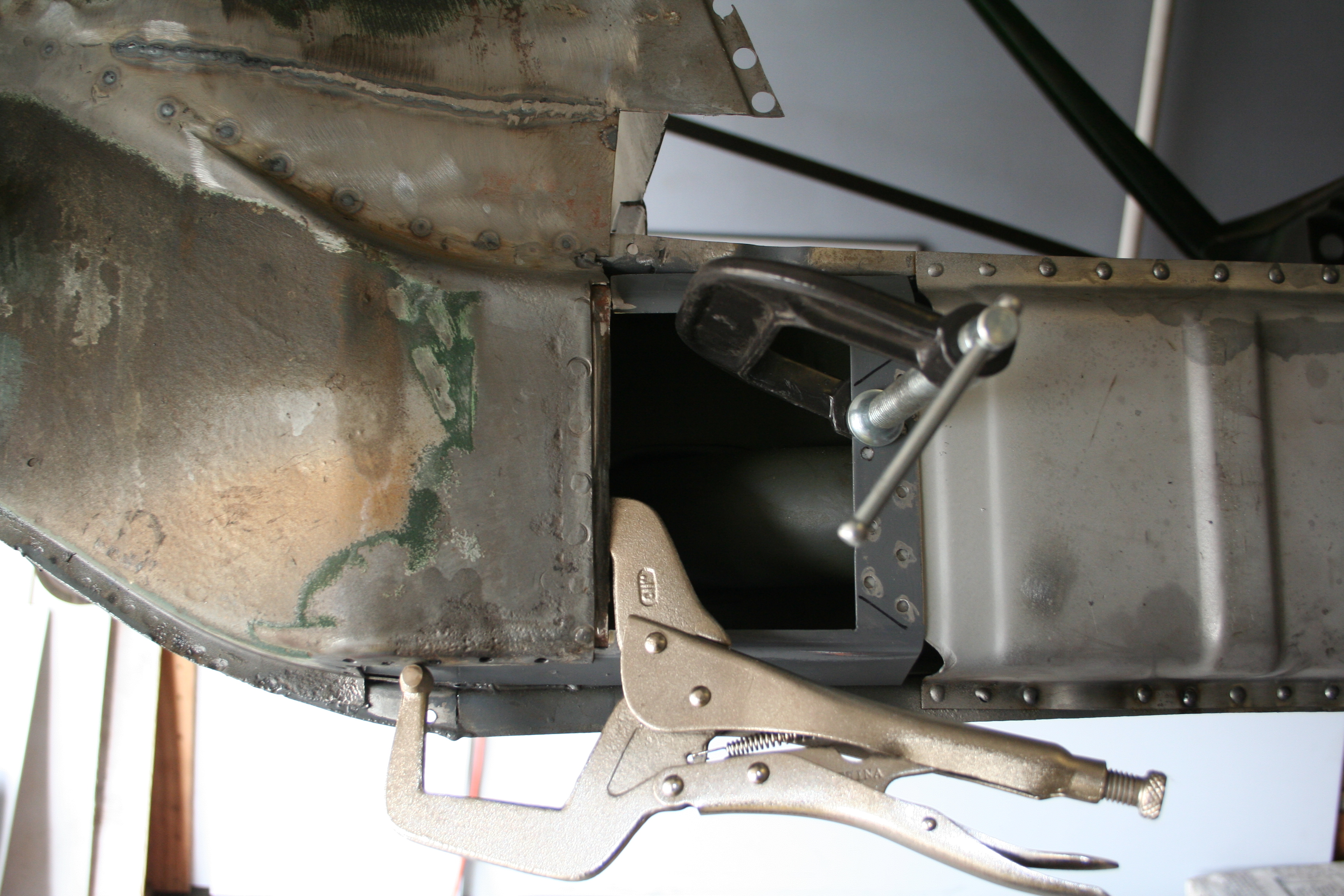
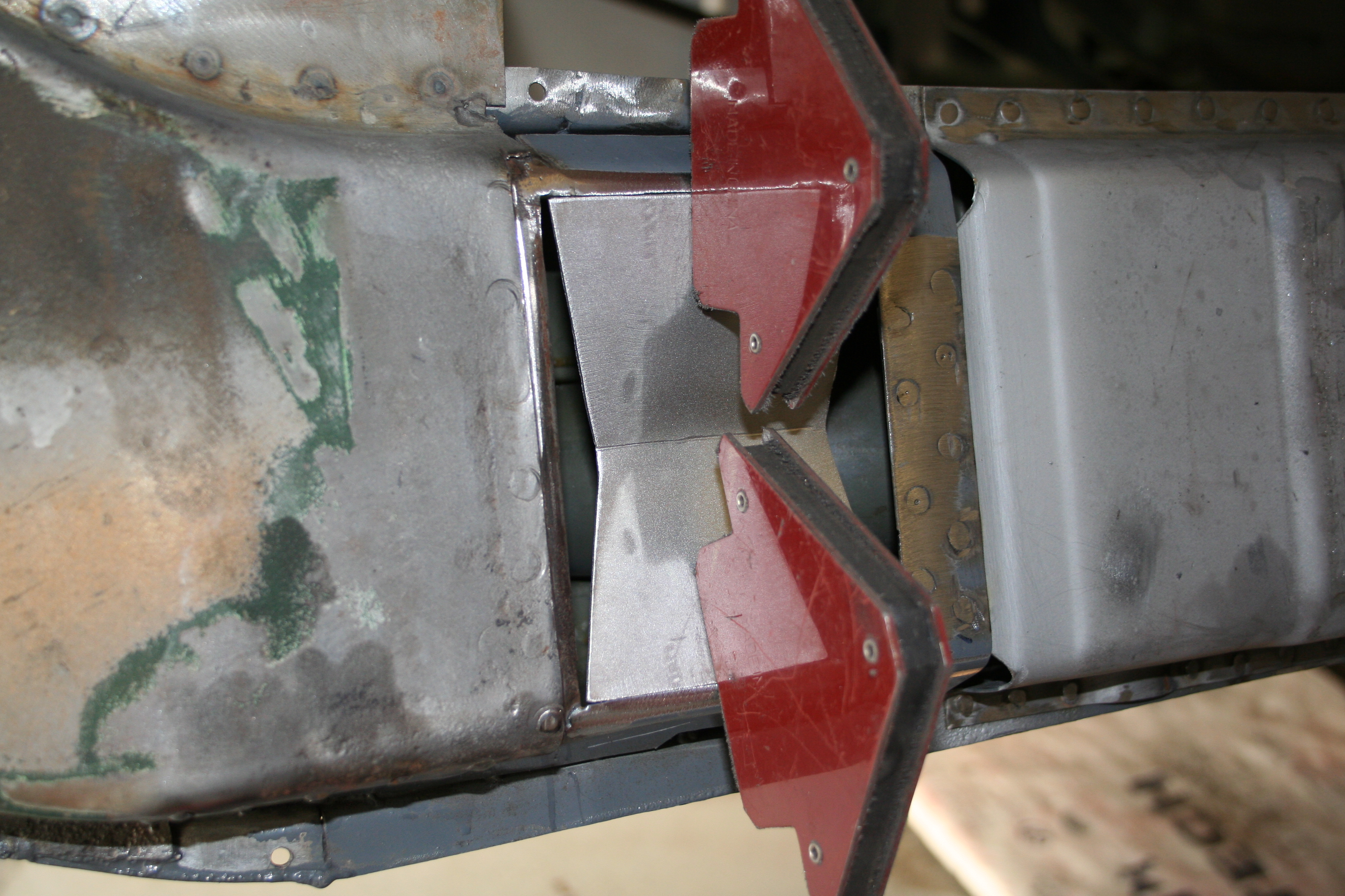
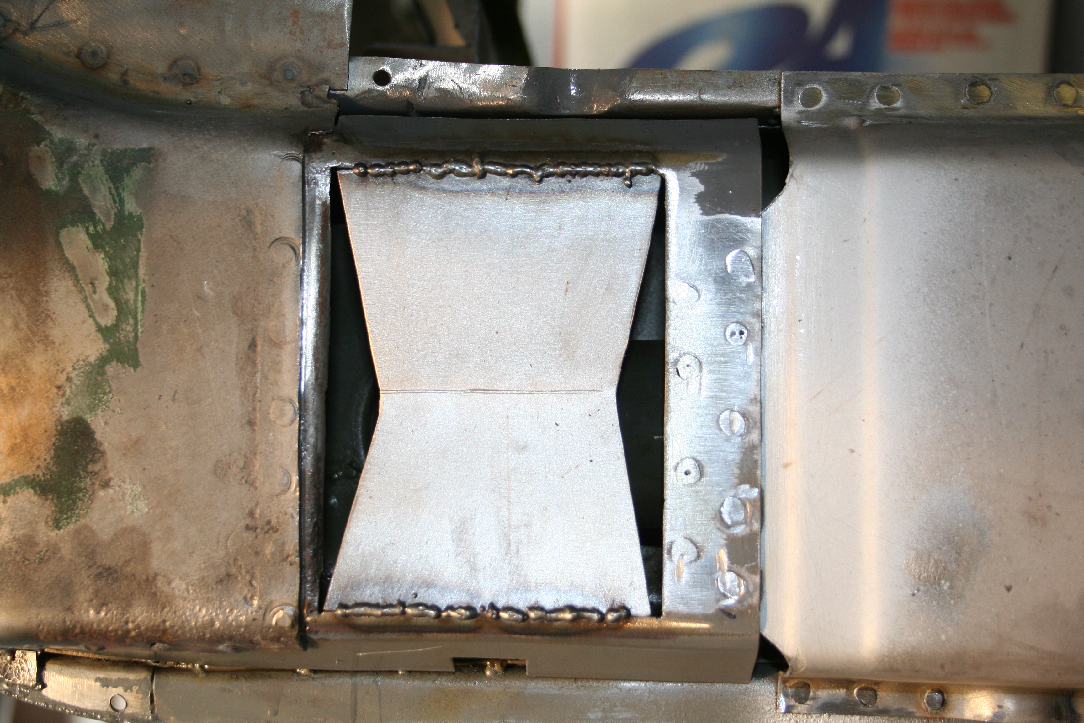
Now I am putting the old next to the new and transferring a cut mark to the new part. Be generous and make sure you leave a few millimeters of extra metal on the new part so that you can trim to fit once the part is cut out. Remember, measure twice and cut once! Read more about front trunk repair work here Onto the Front brakes...Ok, first let me tell you what my plan is with regards to the front brakes. Since I am using a 911 front suspension with the 3.5" caliper spacing mounts, and assuming I want to use bolt on Porsche calipers, that leaves me with the all Aluminum "S-Caliper" or the later Steel "A-Caliper". While I would love to use the S-Caliper for both lower weight and coolness factor, they are expensive to buy and expensive to refurbish. I think a used core set is around $400+ and then it's likely that the pistons are rusted and need to be replaced. That is another $160 or so. You would then need to replace the outside hard lines (not sure of the price but it's not cheap). Then you have the normal costs of cleaning and replating plus seals, etc. So for right now I am not going to go that route. Maybe someday in the future. So I am going to go with the A-Caliper. It is about the same size as the S-Caliper, maybe even a bit stiffer, but heavier. It basically was the caliper used up through and including the 911 Carrera. The Carrera did actually use a slightly different version of the A-Caliper (wider and with brake wear sensor). I purchased my calipers from a local guy who parts out 911s. They were in really great shape and frankly I could probably just cleaned them up and used them. But I want to do a full rebuild. Here is the point at which most people would say to let someone else do this. And mostly they are right. Not from the perspective that it can't be done, but that it can be a pain in the ass and those who do it professionally do a great job. In my opinion the number one person to do this would be Eric Shea at PMB Performance... I have a need and desire to do as much of my own work on this car, so I am not going to ship the calipers off to someone else. But if I was, it would be Eric who would do the work. The nice thing about Eric is that he is very willing to help others do the work themselves. He also sells rebuilt kits and other rebuild supplies. So since Eric is helping me out, I am trying to buy as much of my rebuilt items from him. He offers a great service to the community. Anyhow, onto the rebuild...
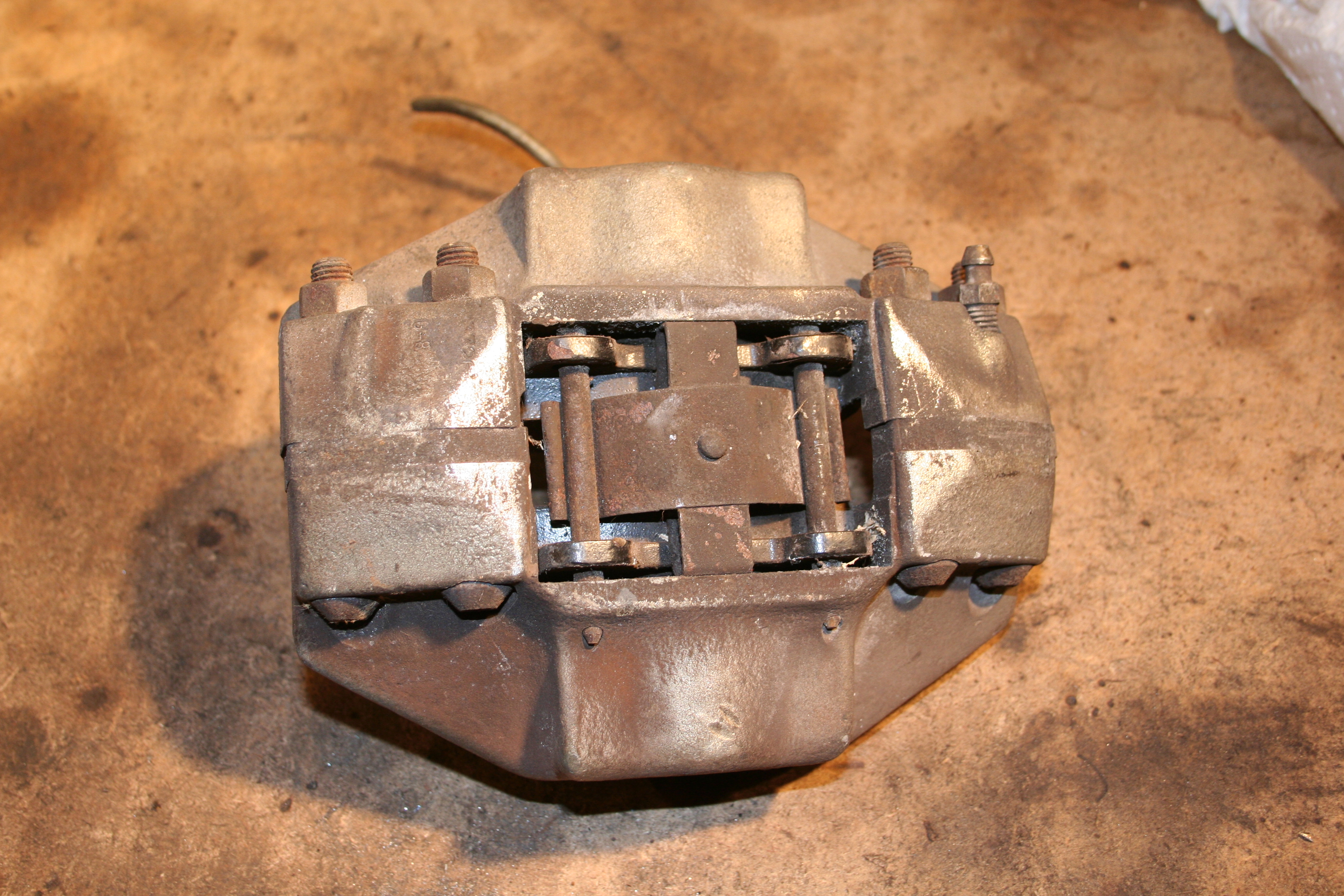
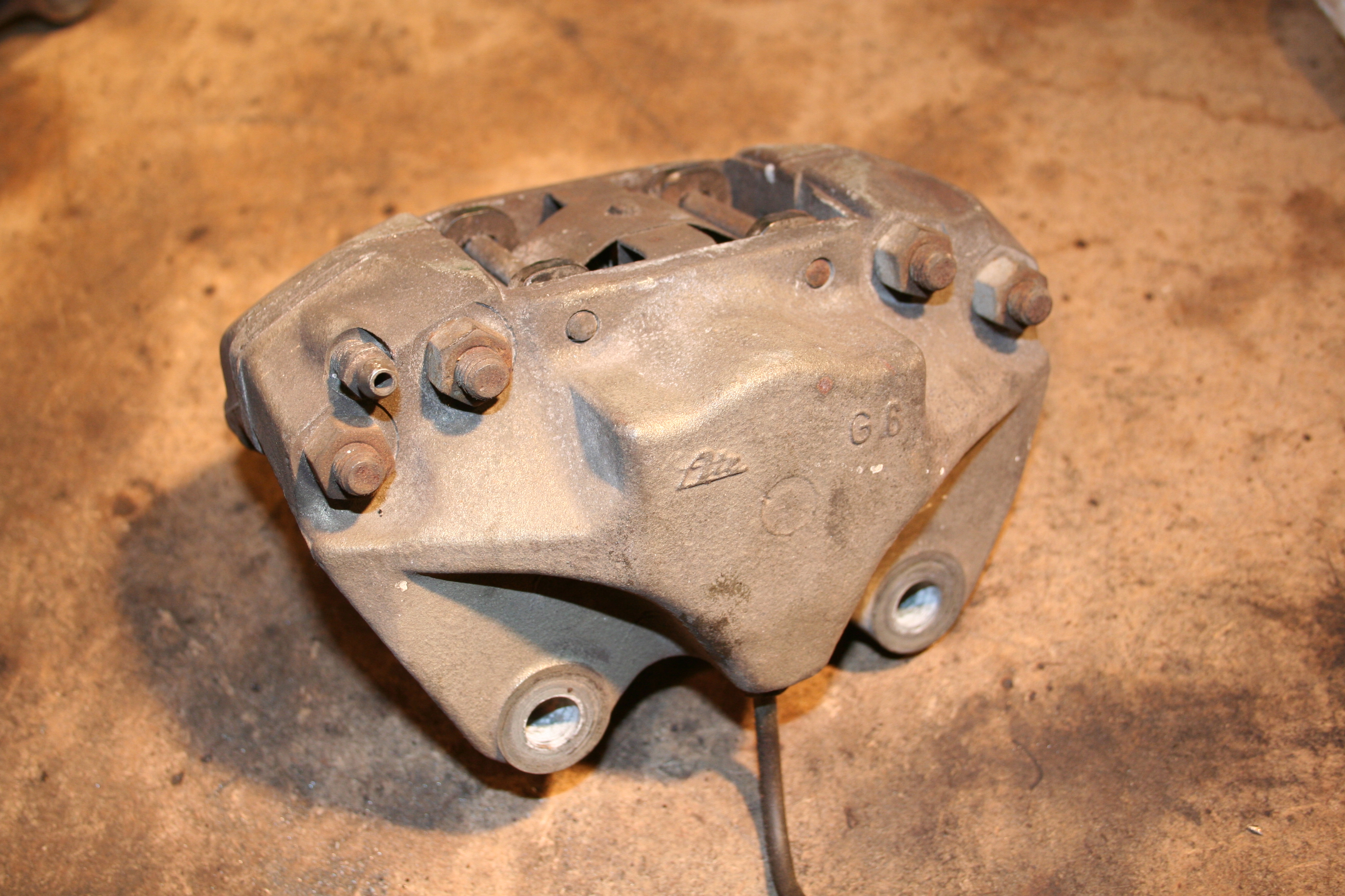
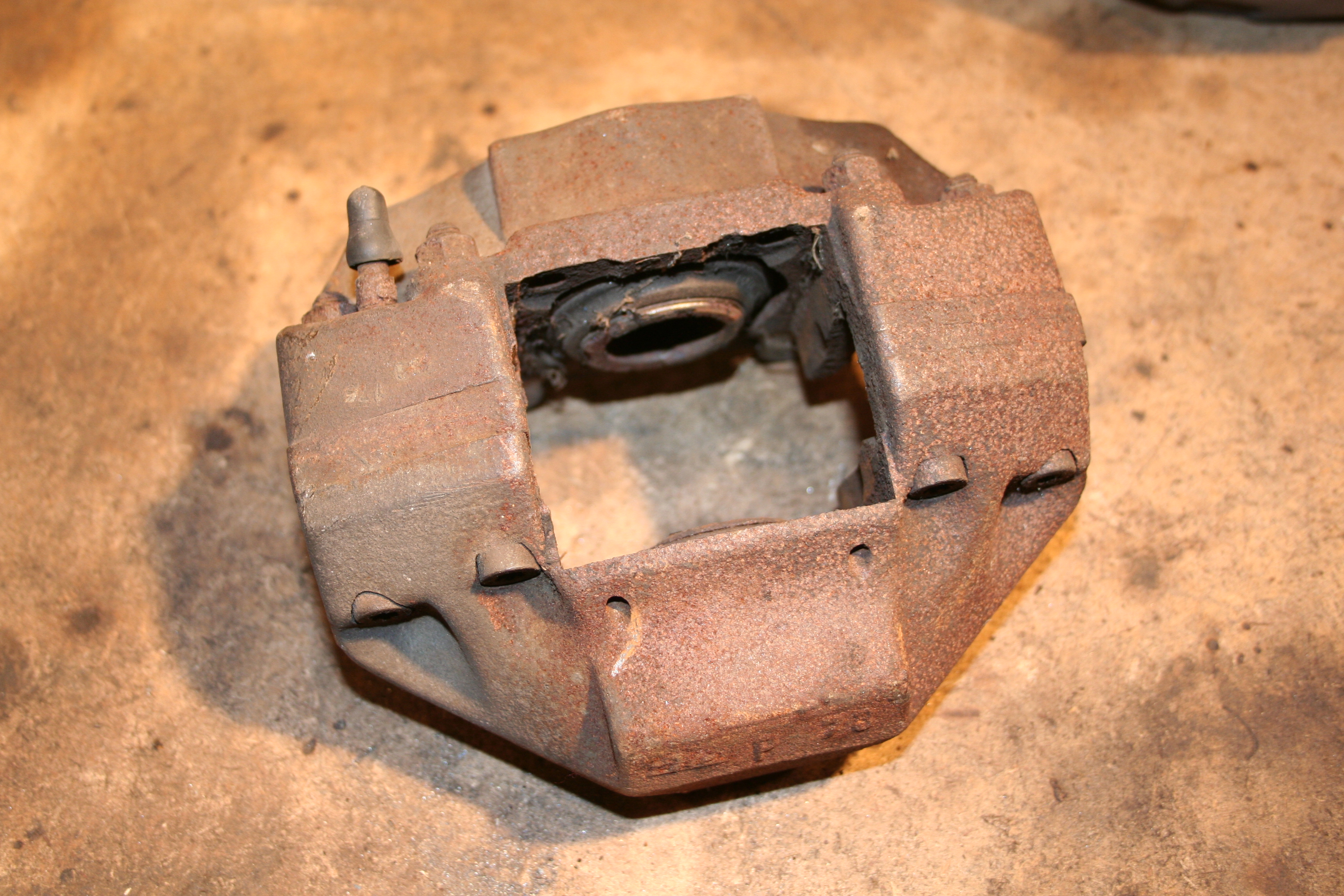
Basic ATE early A-Caliper with 3.5" mount spacing.
Notice the pins and related hardware that hold the pads in place. You can also see the four bolts that hold the caliper halves together as well as the spacers between the caliper halves.
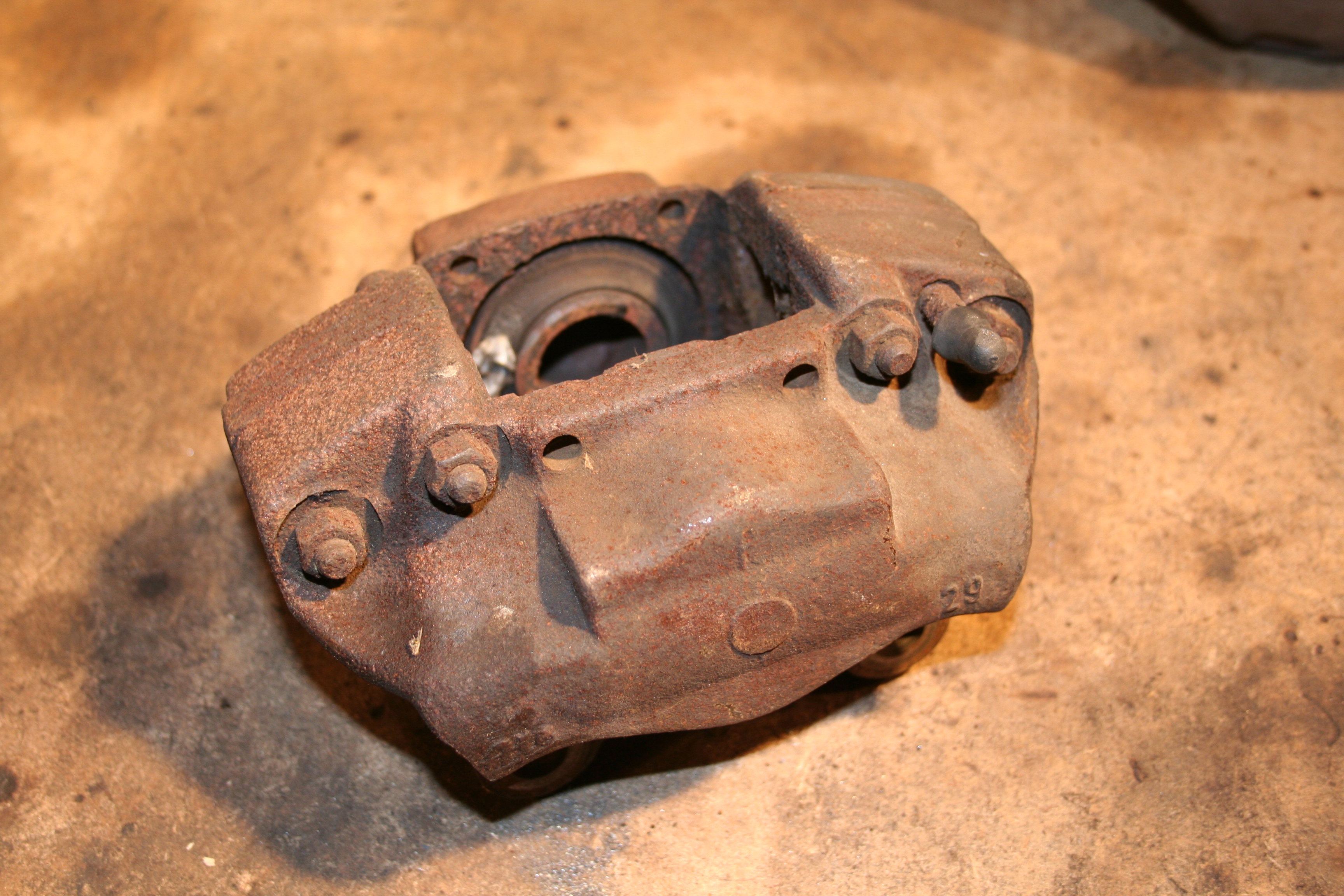
Another view with the bleeder valve.
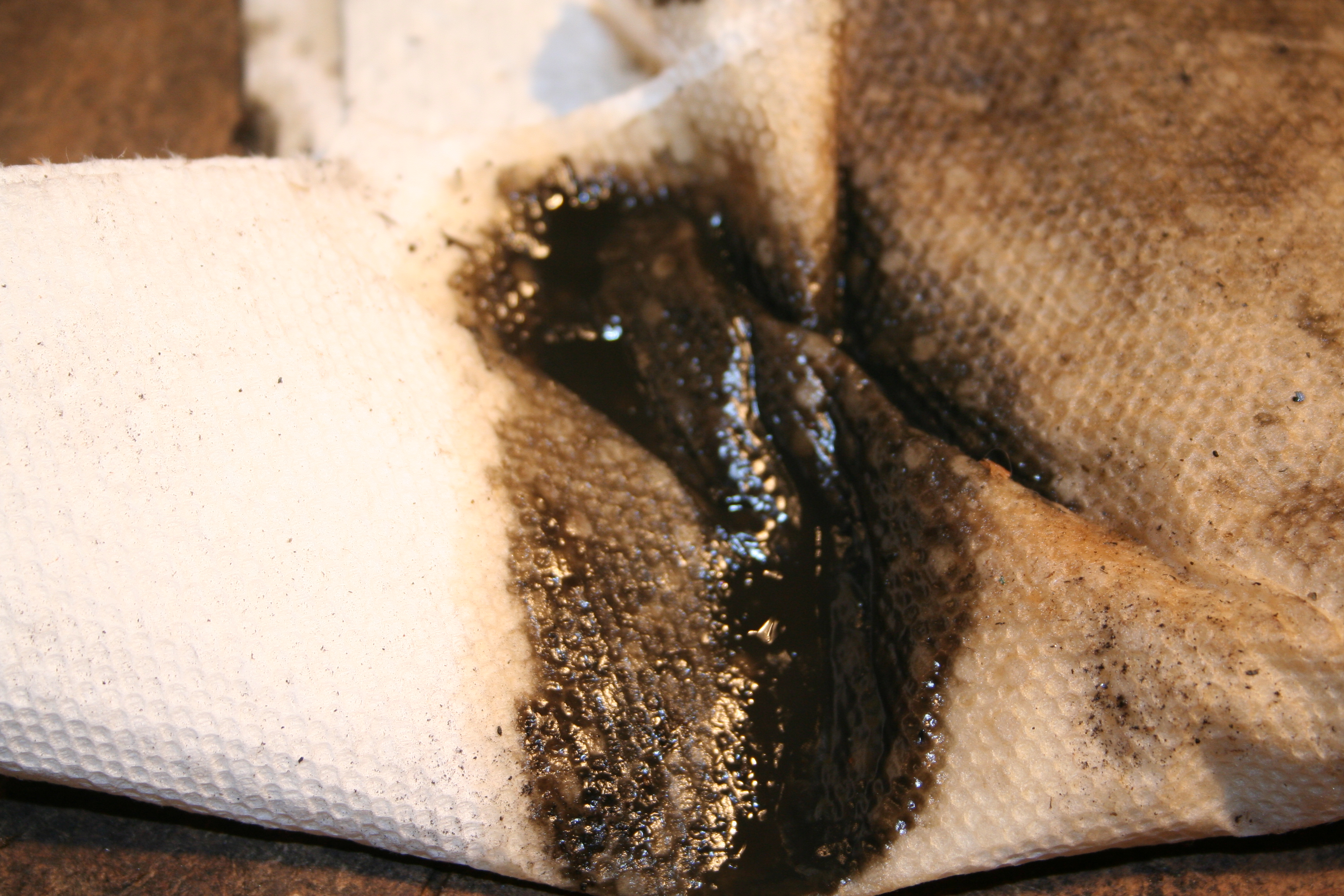
Example of the kind of crap you will find in a caliper that has not had new fluid in years.
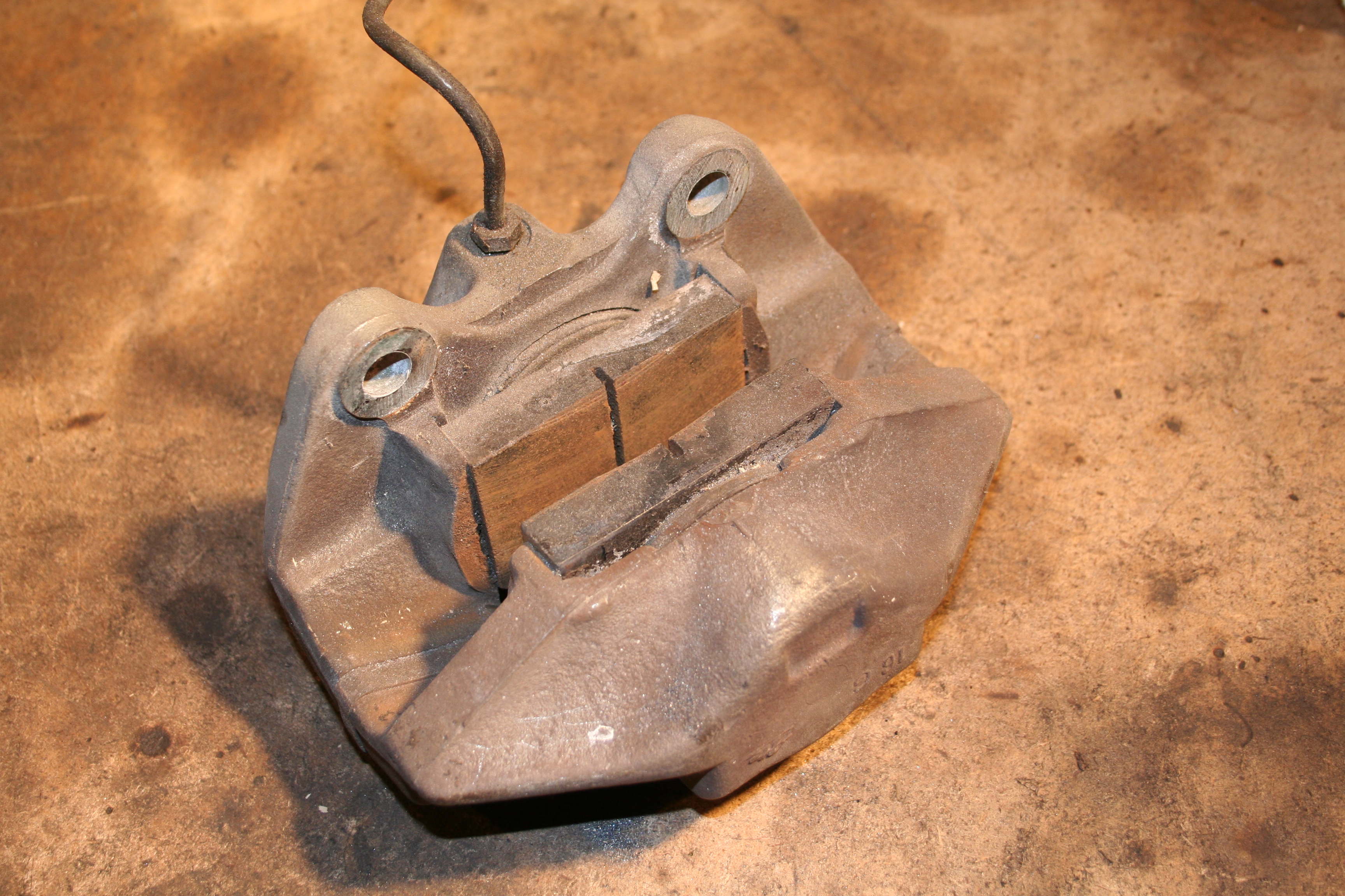
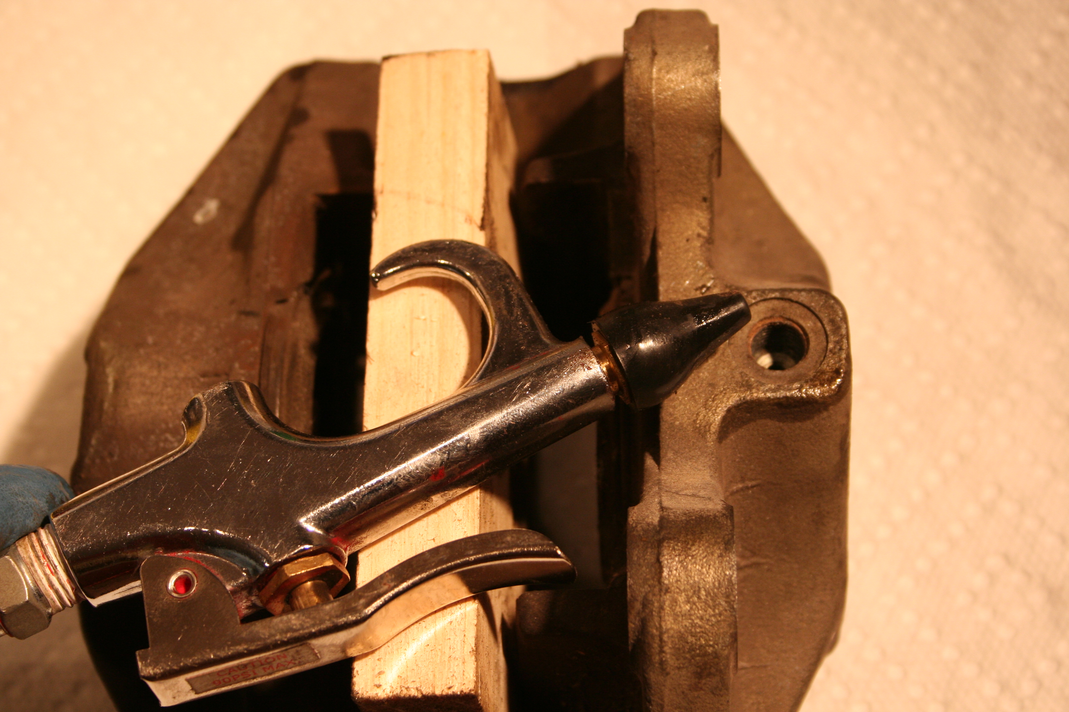
Ok, I am a fan of the compressed air method of removing pistons. The basic idea is that you need to put something in front of the pistons to keep them from rocketing across the room. I am using a wooden block. Then using an air gun (mine is using a rubber nozzle) you slowly pressurize the area behind the pistons. If all goes well and you have a smooth control of the pressure you can ease the pistons out. If you are ham fisted you can pop them out in a very forceful way. With this being a multi piston caliper, the trick is to not pop just one out, but to ease both out to the point they are about to fall out. That way most of the work is done for both pistons. But sometimes the pistons will not budge even if using over 120 psi or air. In that case...
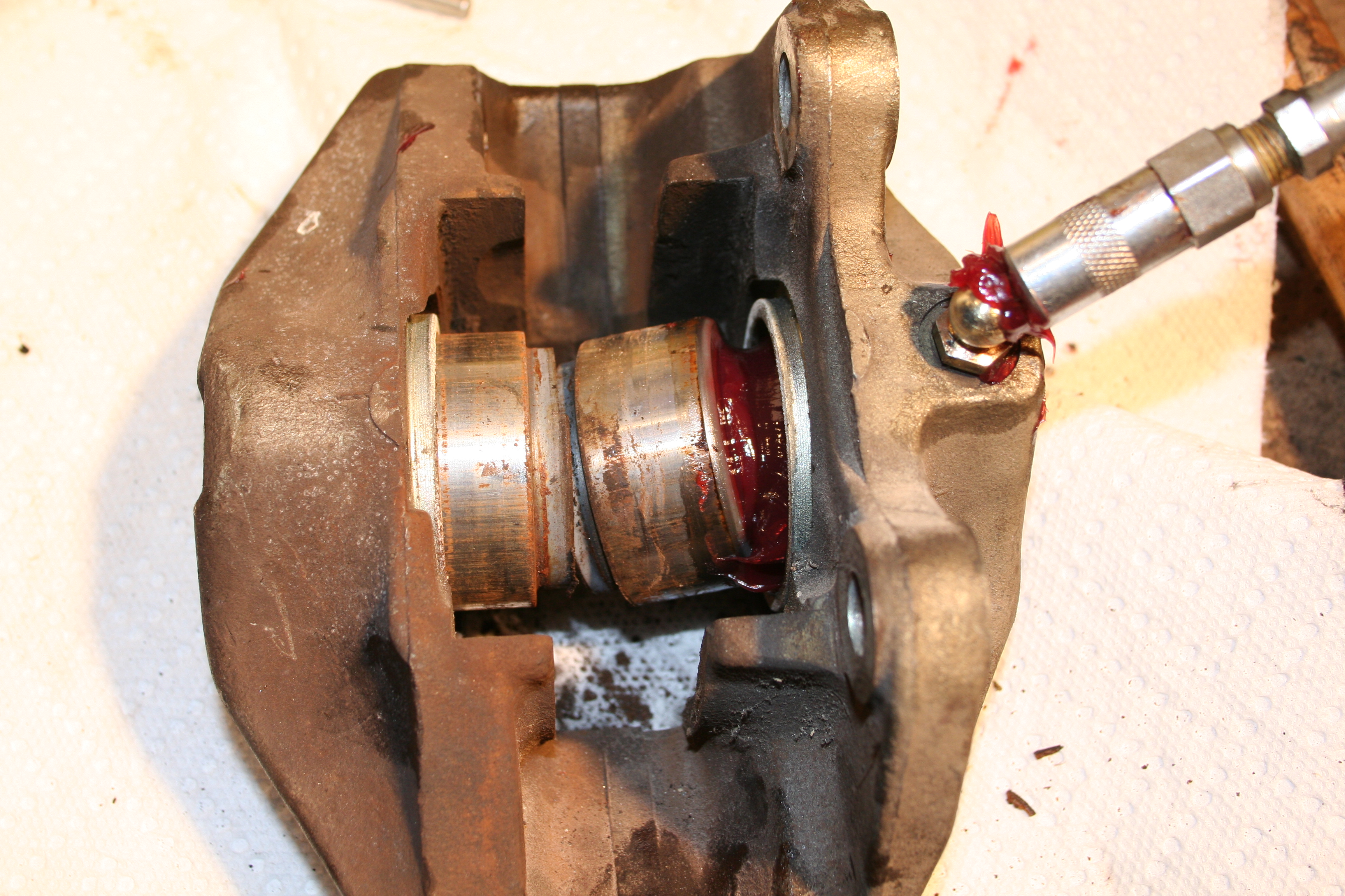
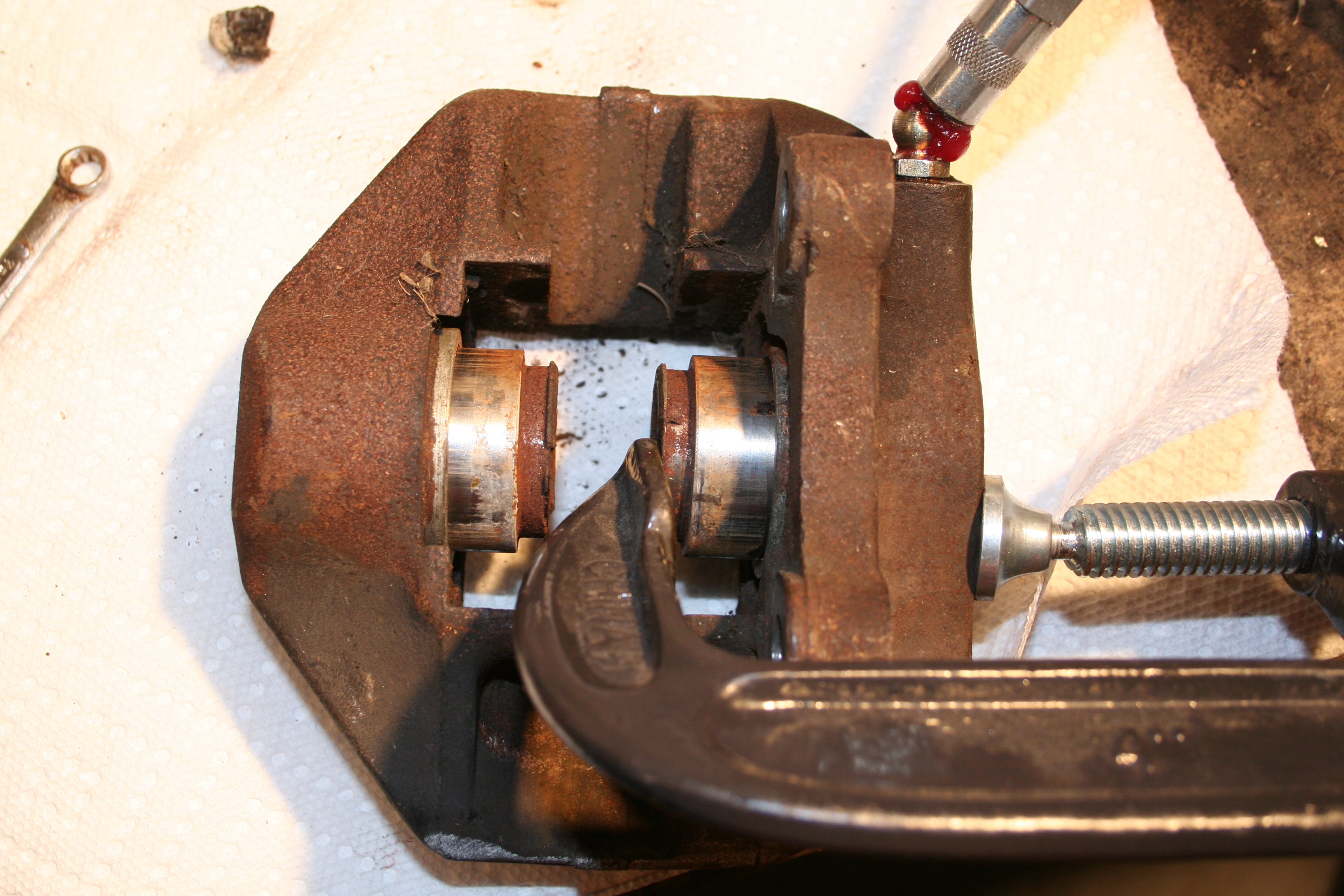
You move onto option two. That is to use a grease gun to push the pistons out. With the grease gun you are able to put much more pressure on the pistons than you can with compressed air. You need a way to get the grease into the calipers. These ATE calipers use an M10 thread (I think the thread pitch is 1.0), so my solution is an M10 Zirk fitting. Then I just hook up a regular grease gun and start pumping.
Here I have moved one piston out some, but I am clamping it in place, so I can move the other.
I move the clamp back and forth and hopefully move them both out a bit at a time. Eventually one is going to pop out. You can put it back into the caliper just enough to match up with the seal, clamp in place and pop the other piston out. You may need to take a channel lock wrench to pull out a piston. DO NOT clamp anything on the piston outer surface. If you must clamp onto the piston try to protect it with a rag and clamp around the dust seal area. If you can't rotate it out relatively easily then you haven't pushed it out far enough. At this point if you are not going to split the caliper, you can clean stuff up and using a standard rebuild kit, install new seals, etc. But I wan to split the caliper as I am going to replate everything.
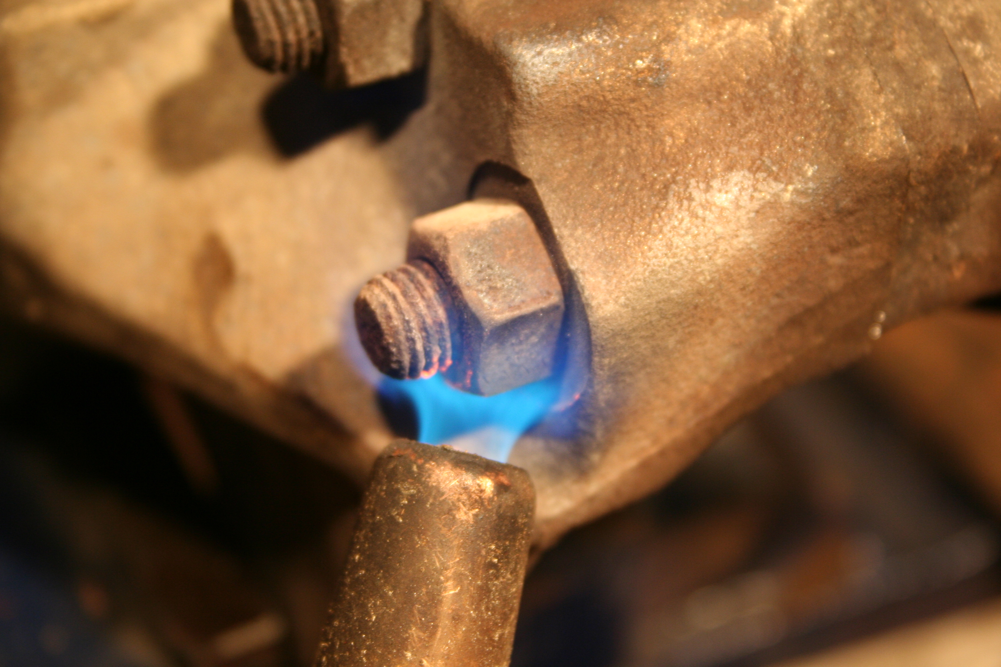
The four cap head bolts and associated nuts are of an odd design. First they are M9 hardware. New M9 hardware is pretty much unobtainable. You may find an odd bit here and there, but so far I have not been able to find replacement M9 hardware. So you need to keep the existing hardware. The other odd thing is that the cap head uses a Ribe style head. This is sort of like a Torx head, but it has square edges. Ribe bits are available and you should NOT try to use Torx bits on a Ribe head. You may think it will work, but you will strip out the head. On top of all of this, the cap head bolt uses a relatively small Ribe size. It is a 6m Ribe head. This is small for a M9 bolt. The bottom line is that it's very easy to tear up the head of this bolt if you are not careful. The way to do this is to heat up the nut to help loosen it. I used a MAPP gas torch and applied heat to each nut for about 5 minutes. It will heat up the entire caliper and the nut really is not going to get red hot as the entire caliper acts as a huge heat sink. Once you have heated them up, let them cool down before you try to remove the nut.
I noticed an interesting thing as I heated the nuts. I heated the caliper enough that it started to sweat out small bead of what I think is lead between the caliper halves and the spacer. I suspect that when ATE built the calipers that they may have "tinned" the mating surfaces with a bit of lead for some reason. You can see the small beads in the photos above.
Ok, after the calipers cooled overnight, I sprayed some "PB Blaster" on the nuts to help loosen them. Not sure if that worked or not. Then let that sit all day. Then in the evening I removed the nuts. The trick according to Eric Shea (and I did this) is to put the Ribe bit in a wrench, but hold he bolt still. Then use an impact wrench on the nut end. I learned that the best way to do this is to make 100% sure that the Ribe bit is all the way into the socket head. Make sure it is completely perpendicular in every way and then hit the nut with the impact wrench. You really want to make sure that you don't twist the Ribe bit in the bolt head. If it doesn't break loose after one or two hits with the impact wrench, stop before you screw up the bolt head and do another heat cycle. In the photo above, you can see the bolts and nuts (which apparently are black oxide plated), the split calipers and the spacers.
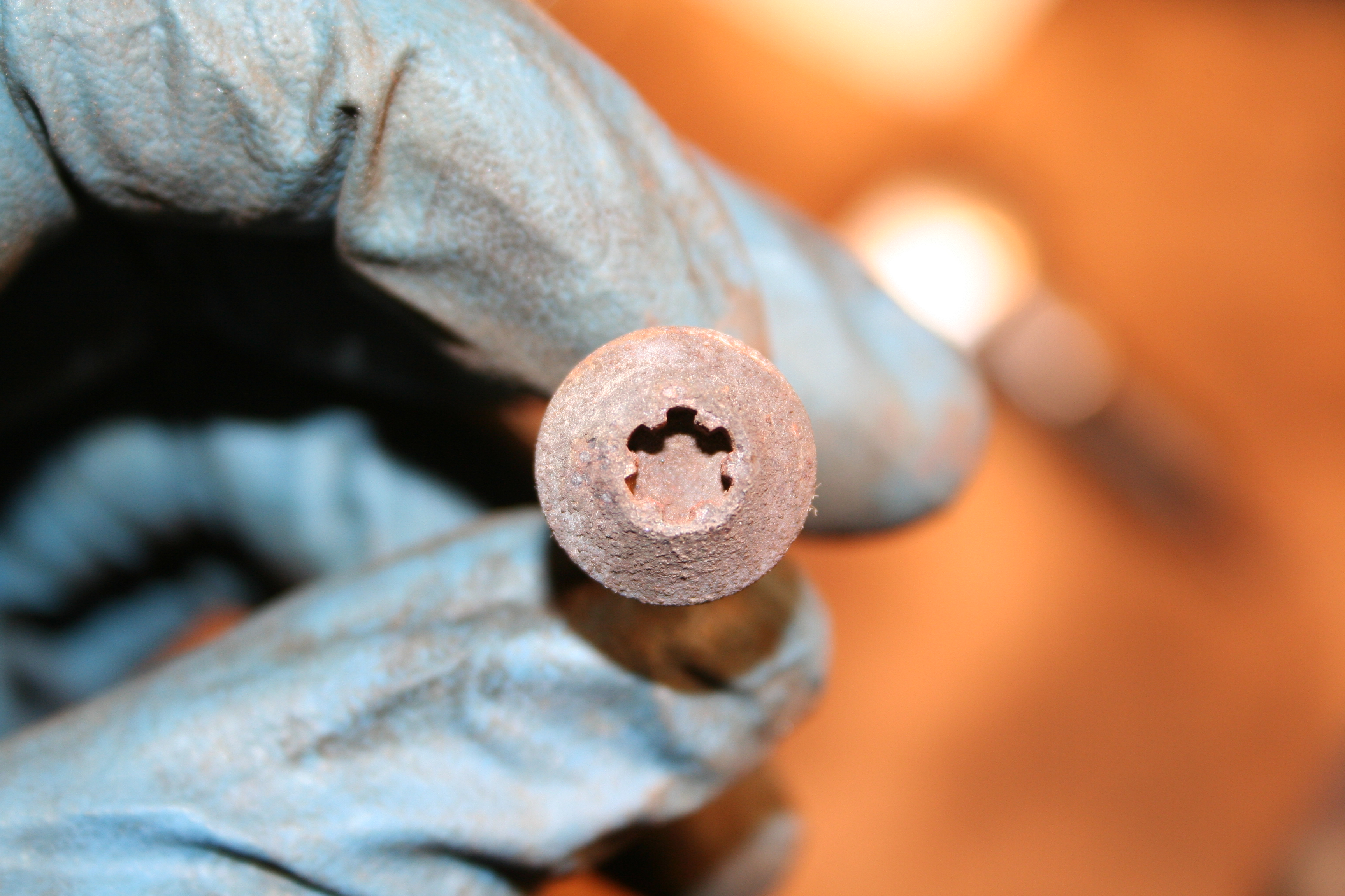
Here is a 6mm Ribe bit.
Here is the M9 bolt with a 6mm Ribe head. Note the square edges which are not like the round edges of a Torx head.
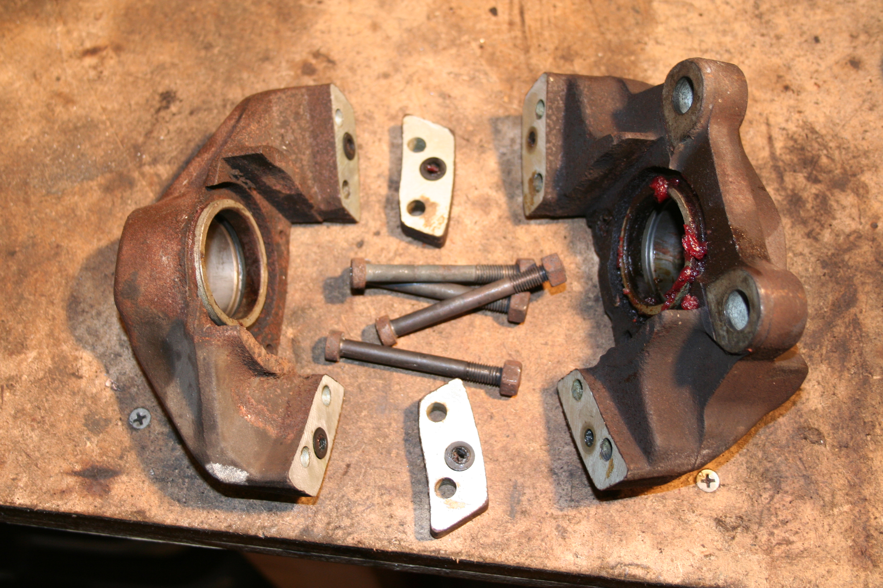
Here is the spacer next to one of the caliper halves. Note that there is a recess in one of the caliper halves as well as the spacer for the small o-rings. Normal caliper rebuild kits DO NOT provide those o-rings as they assume you will not be splitting the caliper. Read more about front brake repair work here Now for the rear brakes...Ok, first let me tell you what my plan is with regards to the rear brakes. As I mentioned above, I am using A-calipers from a 911 for the front brakes. These use 48mm pistons and should be nice brakes. You should always make sure you front and rear calipers are compatible with each other. It seems odd that you need to do this as they are on opposite ends of the car, but what you need to proper front/rear balance. So for example if you put extra large calipers on the rear, you would end up with a balance that is toward the rear and would result in a tendency to lock up the rear wheels prior to the front. That is a dangerous combination. You can try to find the proper front rear balance on your own or you can go with a proven combination. I am using the exact same calipers that Porsche put on the rear of 911s that had the A-calipers on the front. This is a proven combination. So I am using what is generally known as "rear M-calipers". Now is the time to mention that the rear brake setup on a 914 is not like that of a 911. The main difference is the parking brake. The 911 uses a drum style system for the parking brake with the brake rotor working both with the drum parking brake and the rotor for the caliper. The 914 uses a special caliper that combines hydraulics for normal braking and a mechanical system for the parking brake. But both use the rotor and don't use a drum style for the parking brake. So if you move to the 911 caliper, you loose the 914 parking brake setup. There are a number of solutions to this, but the most common is to modify the 914 rear swing arm to accept the 911 parking brake hardware. This is generally an easy modification. The hardest part is the cabling system. That is because how the 914 parking brake cable is mounted, it's length and how it terminates is different than the 911. This results in many solutions that range from a replication of the 911 cable, to systems that use a bell-crank to some newer use of 944 parts that have a similar parking brake setup. I plan to use the 911 parking brake with some of the 944 parts. Here is a typical rear M-Caliper. Note that this uses the later style pistons (they are deeply cupped). The earlier style does not have the deep cup and had a built in "knock back" mechanism. The later are considered to be slightly better as the piston does not heat up as quickly as the earlier style piston.
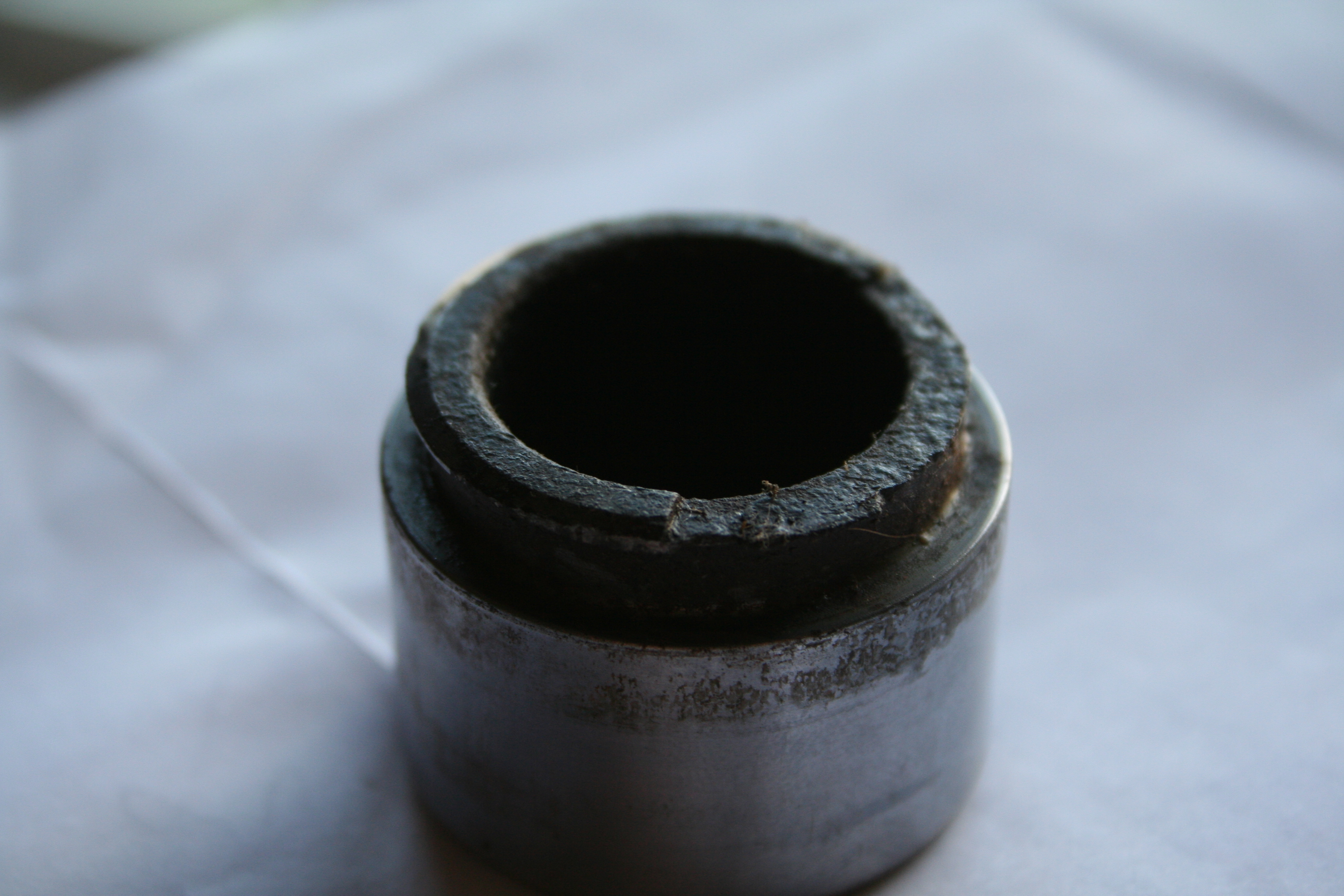
The process is pretty much identical to the front brake. I will mention that these use M7 hardware instead of the M9 hardware of the A-Calipers. M7 is just as impossible to find as the M9. The only upside of the M7 bolt is the it also uses the 6mm Ribe head, but with the smaller M7 nut, it's less likely that you will have problems removing the nut as you might have with the M9 hardware. You still need to heat up the nuts, let them cool, etc. Even if Eric is not going to be rebuilding my calipers, he has been gracious enough to answer some questions for me. The first thing I noticed is that he pistons in my M-calipers are pretty rusted in the area around the dust seals. I emailed the photo below to Eric and he feels that they are reusable once cleaned up, but I may end up deciding to buy new pistons from him before I finish the rebuild process.
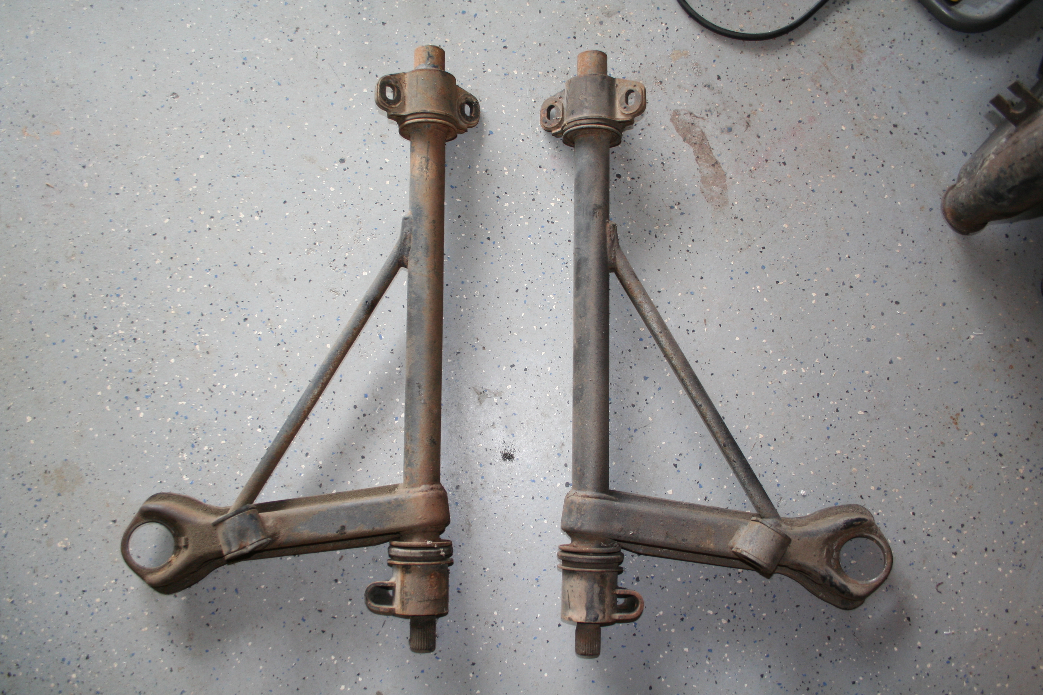
Read more about rear brake repair work here 5/25/2009As part of my overall suspension work I pulled out the front a-arms so I could document them prior to removing the old bushings, etc. I didn't take photos, but the trick is to use a torch and heat the outside section until you can start to hear the rubber sizzle. At that point you can take a wrench and pull the outer section off and then using a screwdriver or similar and remove the bushings from the ends of the a-arms.
Read more about front suspension repair work here In preparation for the modifications to install the 911 parking brakes, I examined my two rear swing arms and noticed an odd difference. The one on the left is the driver side arm and the one on the right is the passenger. Note that the driver side has an extra "tang" that doesn't appear on the passenger side. Also the tang that the hard/soft brake lines mount is different. The driver side is an enclosed hole while the passenger side has a slotted hole. I have been told that the one with the enclosed hole is an early swing arm and the one with the slotted hole is a later swing arm. Assuming you are not looking for an exact match for a specific year, the later arm is the preferred arm as it allows you to remove the caliper and hard line without breaking the connection to the soft brake line. Why is the a good thing? I believe that with the 911 rear calipers in place you actually have to remove the caliper to change pads. This is because the pins that hold the pads in place exit from the caliper in a direction that would hit the swing arms. So you have to remove the caliper, then the pins, then the pads. Being able to do this without breaking the brake line connection allows you to do this without having to bleed the brakes extensively when you change pads.
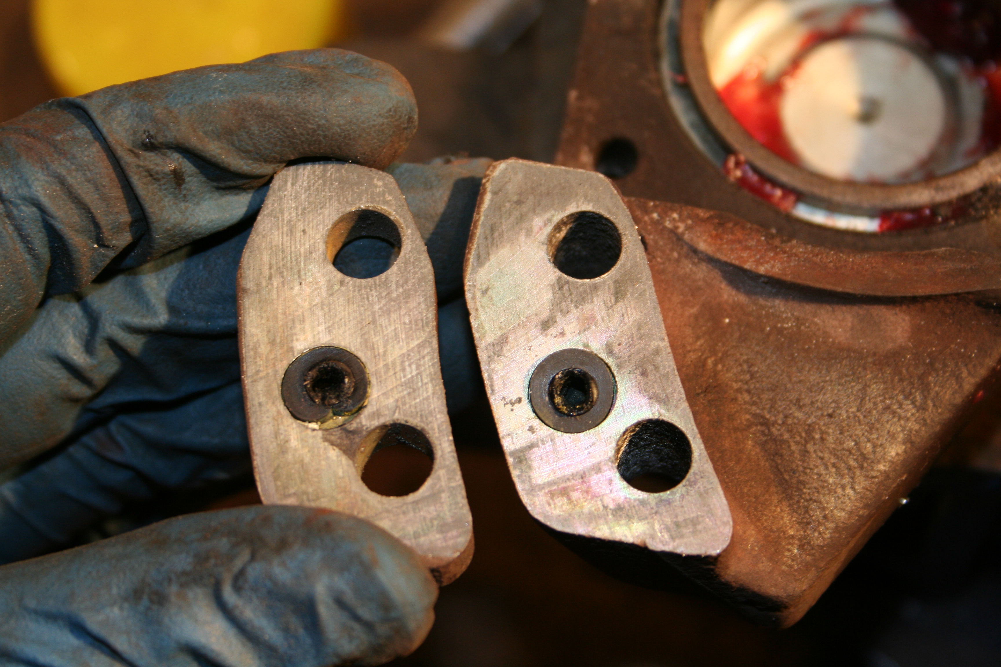
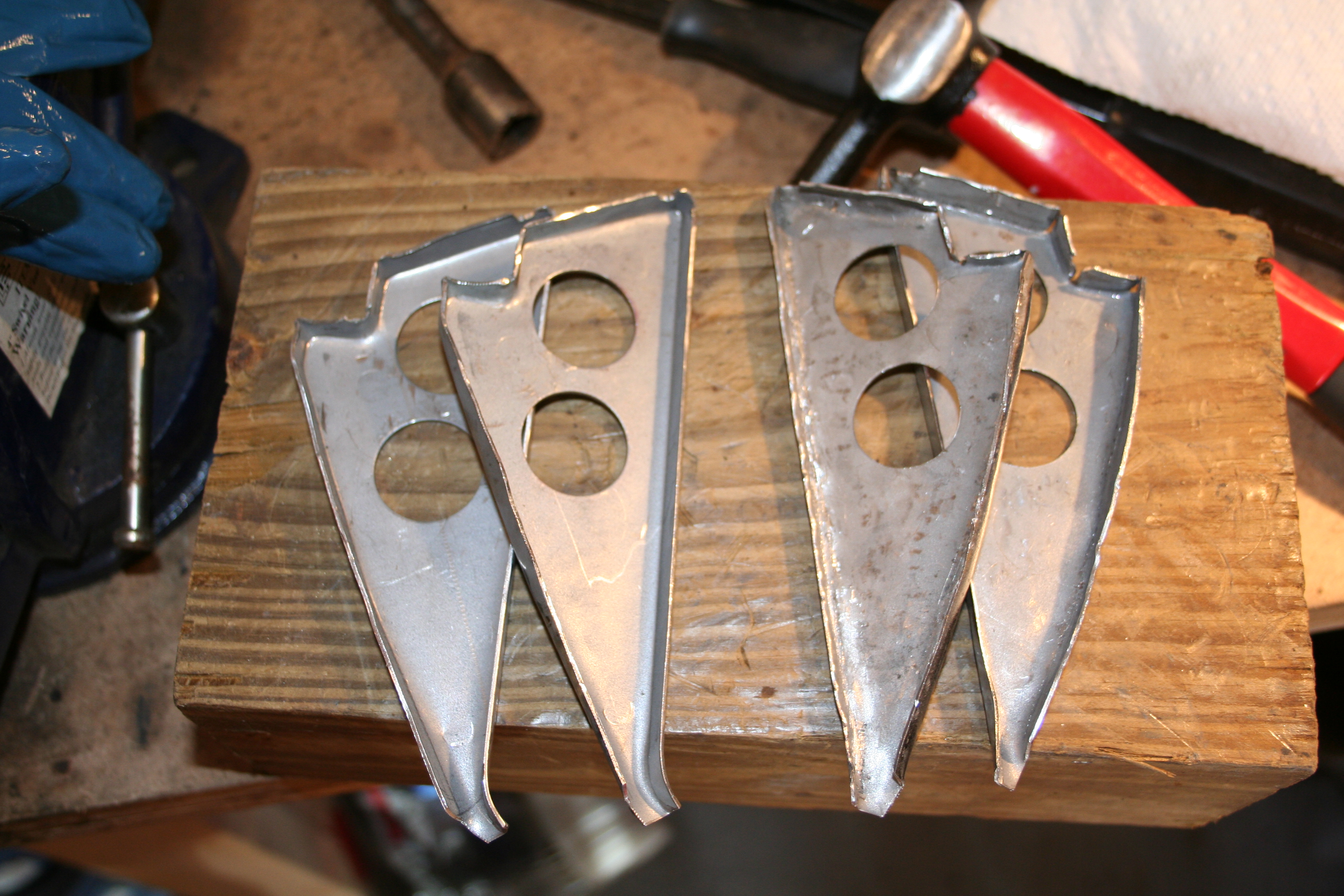
Read more about rear suspension repair work here So I had planned on purchasing new sill plates for both sides from Restoration Design... http://www.restoration-design.com I like Bill at Restoration Design. He makes some great stuff and the price is great. But, he can be very hard to get a hold of sometimes and a number of his parts are out of stock. Unfortunately he was out of the sill plates. So my only option was to purchase from Auto Atlanta... I have nothing against AA. I can't think of anyone who is more devoted to 914s than the owner George Hussey. But is body parts can be expensive. For example the sill plates are around twice what RD would charge. But AA has them in stock and RD doesn't. As it turns out the AA parts did not have the triangular sections already welded to the plates. Additionally they only provide one type of triangular sections. On the car the stamping for the driver/passenger sides are mirror images of each other. But the parts from AA match the driver side and not the passenger side. So I decided that I would flip the flange on two of the four parts so that I could great the mirror images and get the proper look for the passenger side.
The two on the left are the un modified design from AA. The two on the right are the two I modified by reversing the bends. They look a bit beat up as I had to hammer them a good bit, but when weld in place I think they will look better this way. Read more about driver side longitudinal repair work here Read more about passenger side longitudinal repair work here 5/3/2009
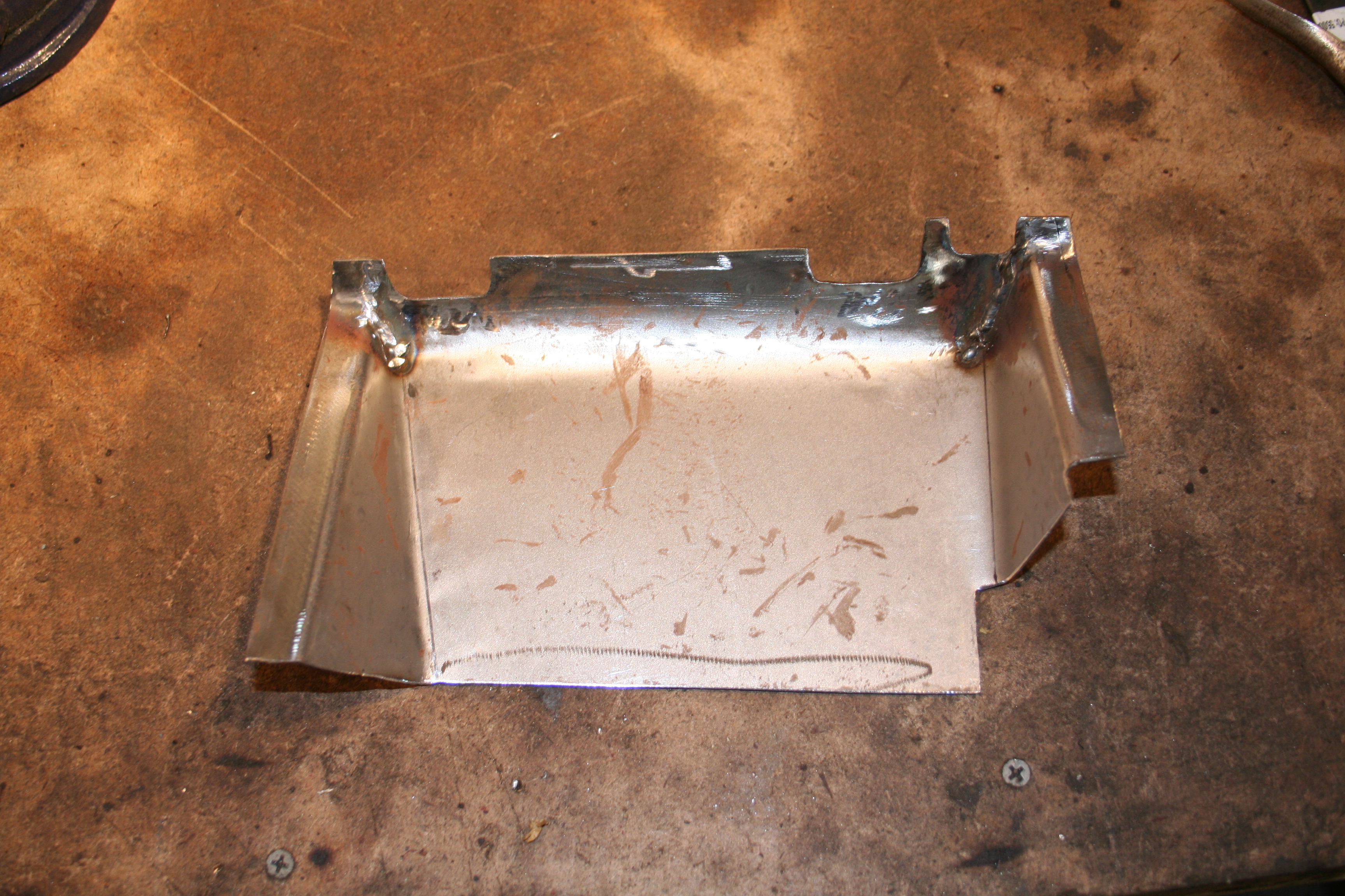
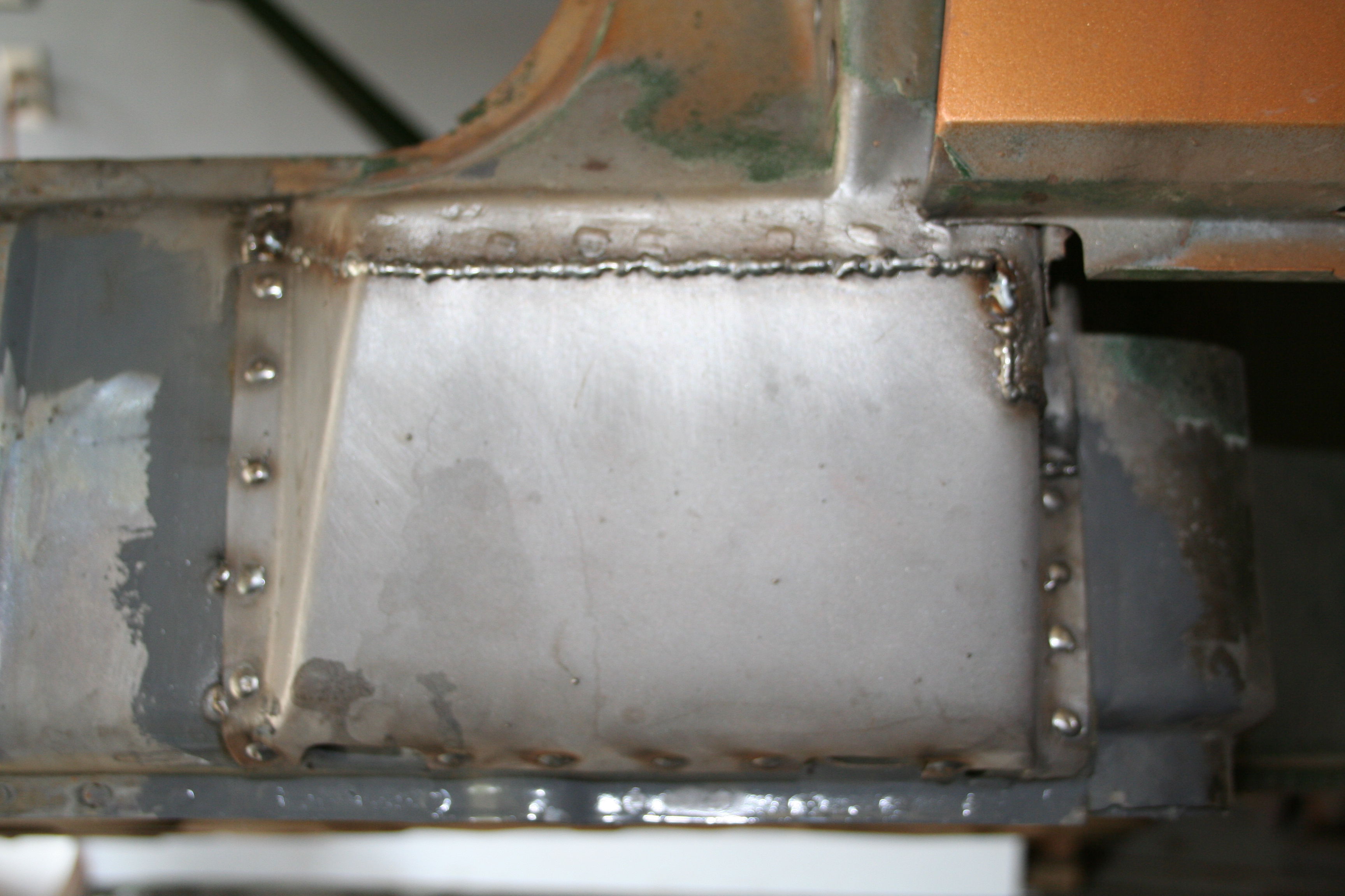
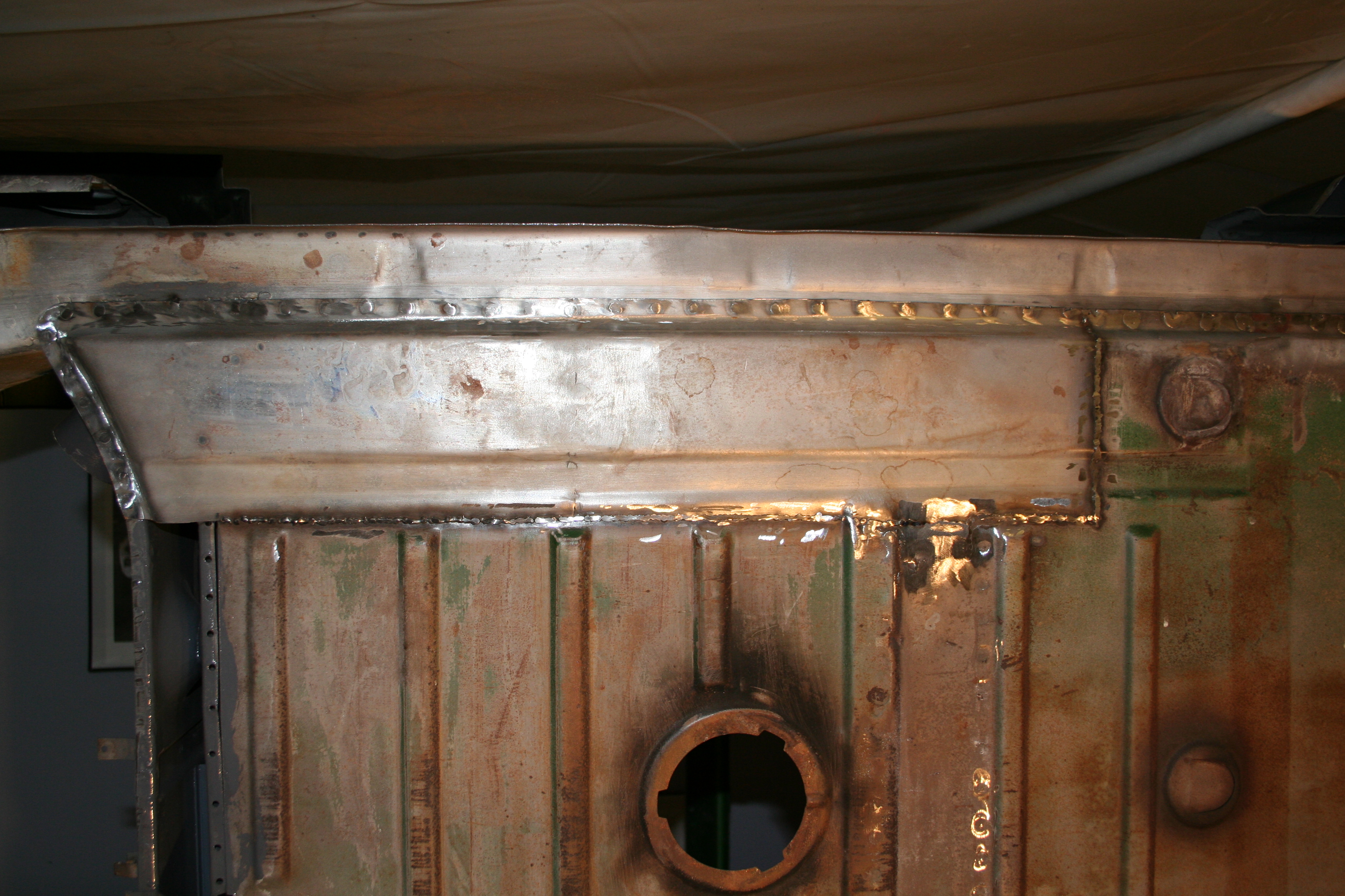
Weld and grind
Interior has welds that don't need to be ground 100% flat.
Media blast and treat with Ospho. It looks really nice at this point if I say so myself.
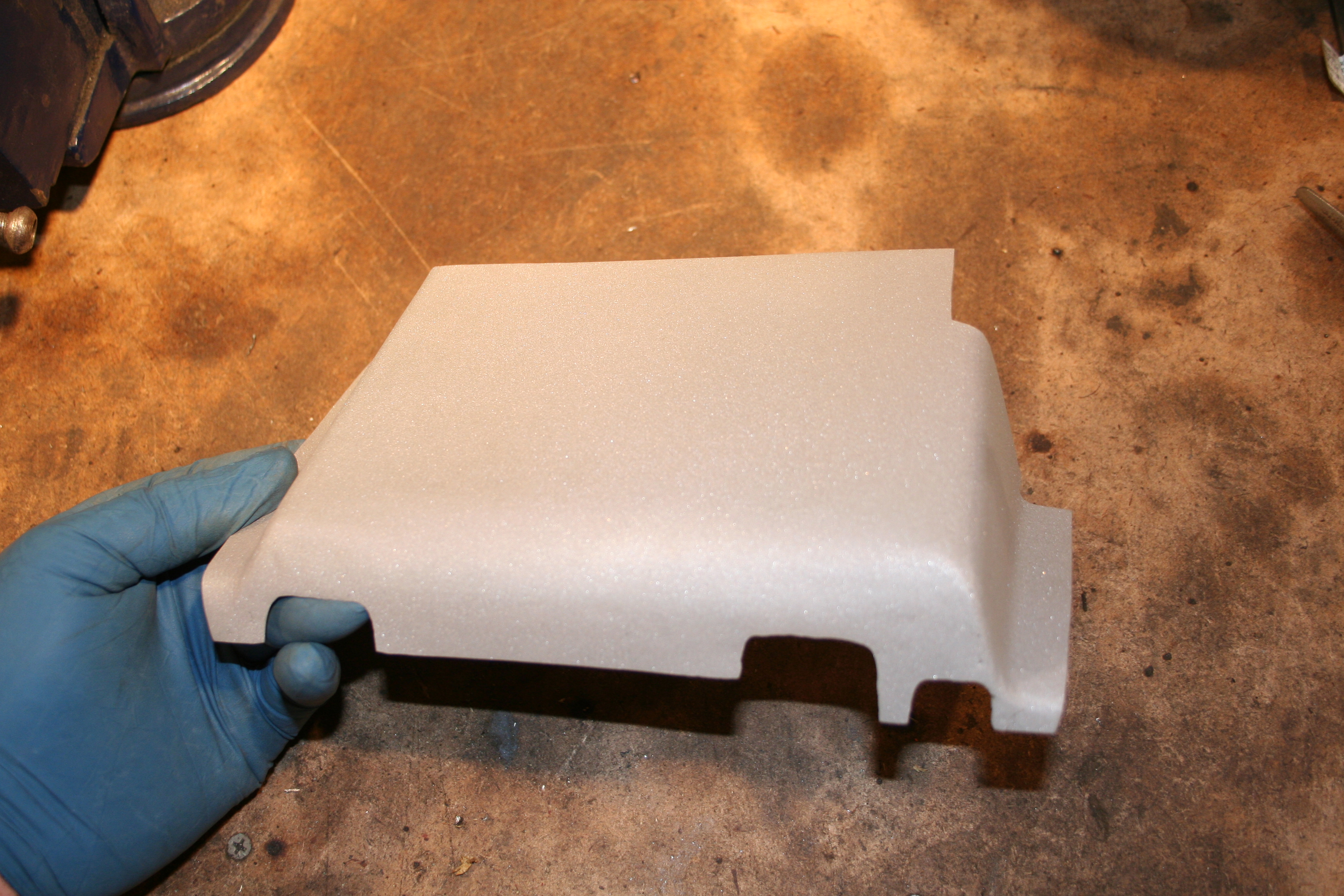
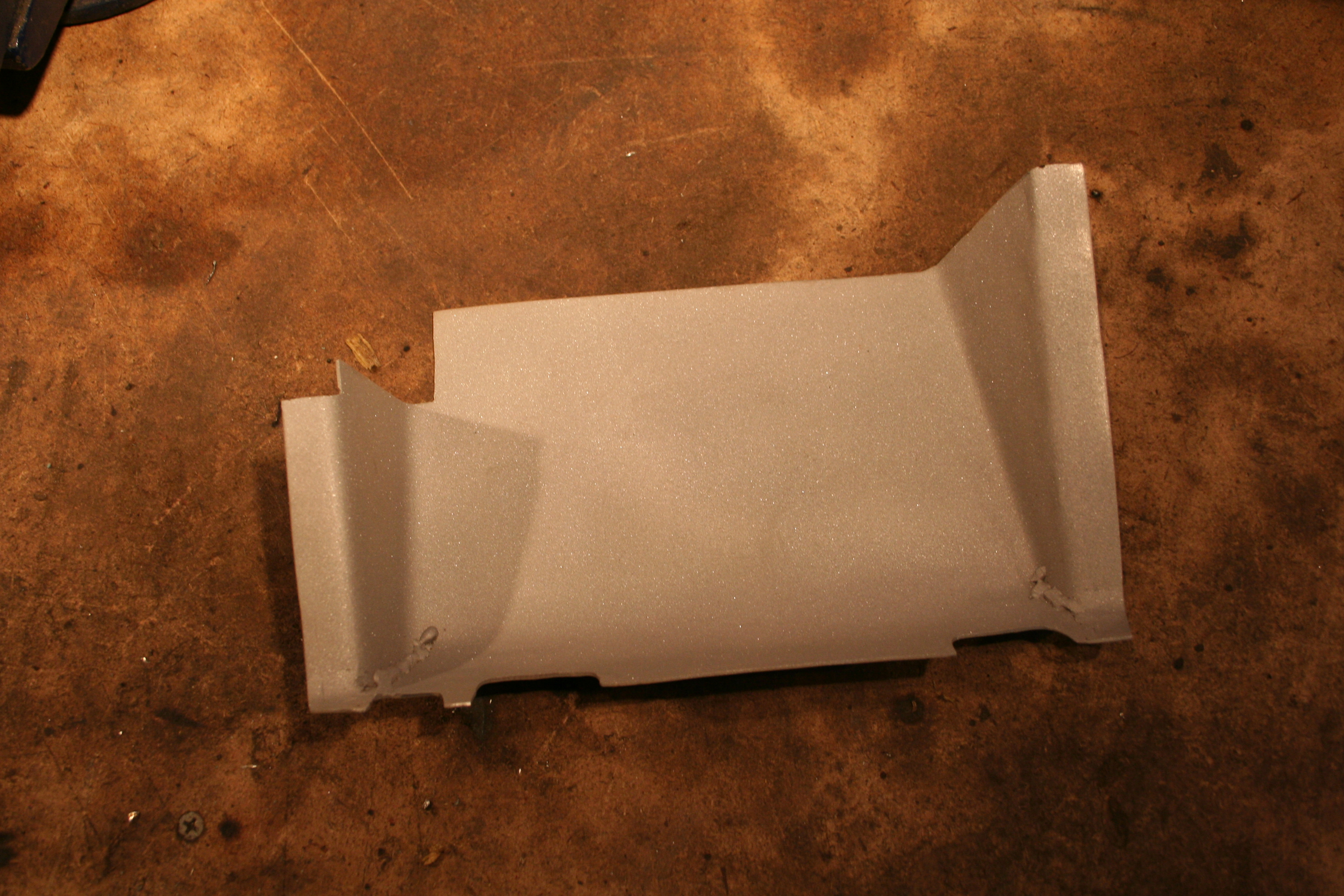
Weld into place. Rosette and seam welds need to be ground down. Read more about passenger side longitudinal repair work here 4/26/2009Almost done with fabrication of parts for this part of the car, but I have one last major part to do. That is the boxed section below the door hinges.
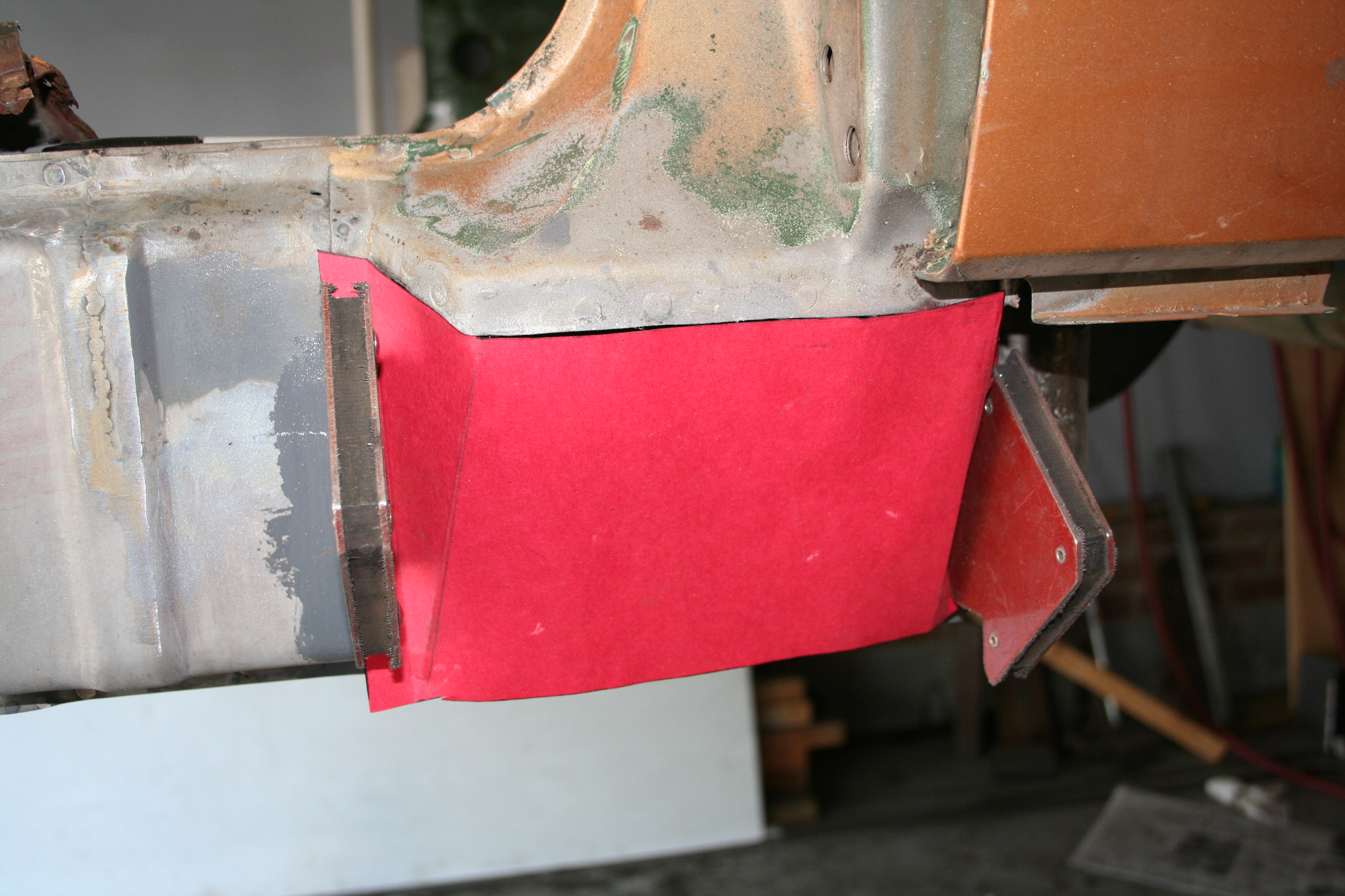
Paper template.
Cut and bend. Note notches match original. Read more about passenger side longitudinal repair work here 4/16/2009Now I need to remove the old sill plate. I do this by drilling out the spot welds as well as cutting away the triangular supports.
Read more about driver side longitudinal repair work here 4/12/2009More work on the jack point...
Driver side with POR-15 to coat the inside of the pyramid.
Passenger side Driver side. Prior to welding I removed the POR-15 in the small area in which I would be doing the rosette welds. You will notice that my pyramid has a non-stock hole in it. I basically added a drain hole and also made it large enough that if debris gathers, I can dig it out. Many people do not replace a rusted jack point and pyramid. In my opinion one of the reasons they rust is that this section is enclosed and can't properly drain. Read more about driver side longitudinal repair work here Read more about passenger side longitudinal repair work here 3/27/2009Final work on the inner layer and welding the jack receiver tube into place.
Final outside layer welded into place.
Welds grinded down, tube welded into place, media blasted and treated with Metal ready. Nice white metal.
POR-15 on the inside. After this dries, I will weld the pyramid in place on both driver and passenger side.
While I had the POR-15 out, I painted the inside of this cavity on the front. After I finish the jack receiver tube and pyramid, I will fabricate the cover for this cavity. Read more about driver side longitudinal repair work here 3/22/2009Final forming of outer layer, welding into place and first steps of welding the jack receiver tube in place.
Here is the finished and media blasted inner layer.
Here is the finished outer layer, but prior to being welded into place. This is the inner surface that has been painted with weldable primer. Note the nut on the bottom. This is for the rocker panel. It has three nuts on the bottom of the longitudinal. The last is right under the jack receiver tube.
Plug welding from the inside out.
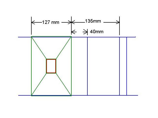
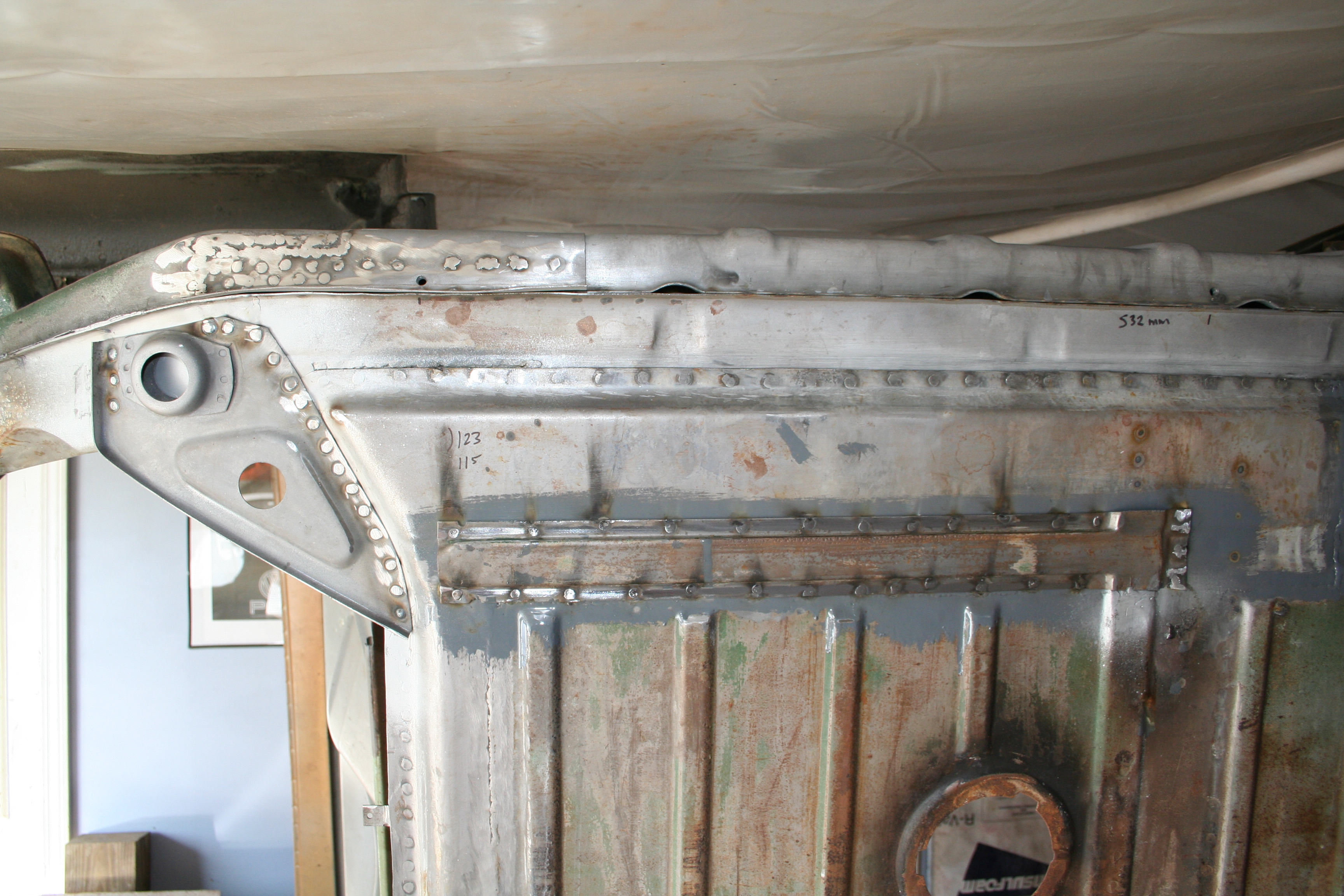
Passenger side with most of the outer layer in place. I still need to weld in the bowtie shaped piece. The passenger side receiver tube and pyramid was totally gone. On the driver side the flange of the pyramid was still there. So I was able to measure it's exact location. The pyramid measured 127mm wide. It's edge was 40mm away from the seam from the front and rear sections. It was also 135 mm away from the top edge of the raised section on the longitudinal. There are multiple raised sections and each are about 150 mm apart. I would not be surprised if it as to turn out that the receiver tube was +/- a few millimeters either way on different cars. There is some evidence that mine from the factory left to right were not identically placed.
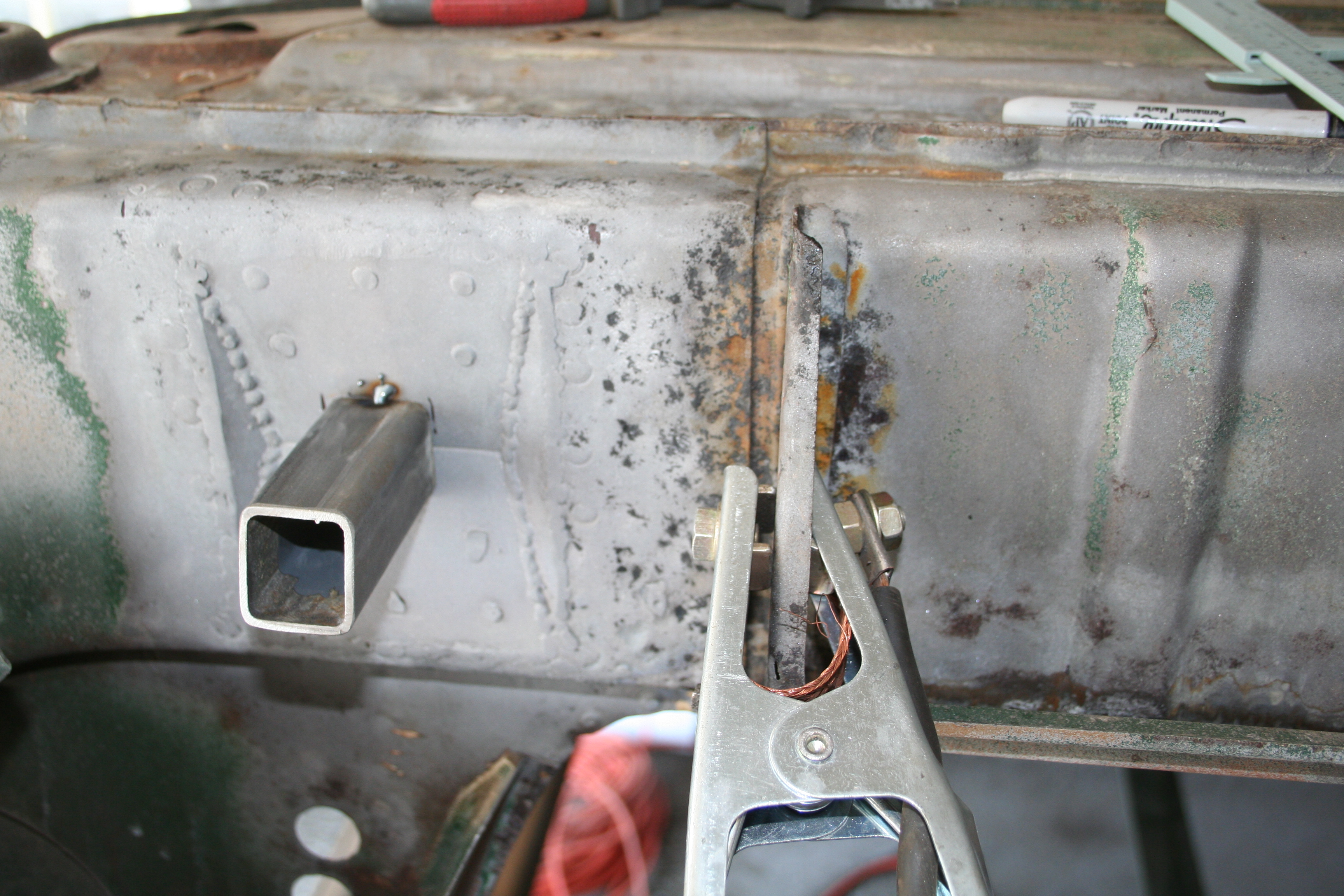
After finding the position I tack welded it to hold it in place. Then...
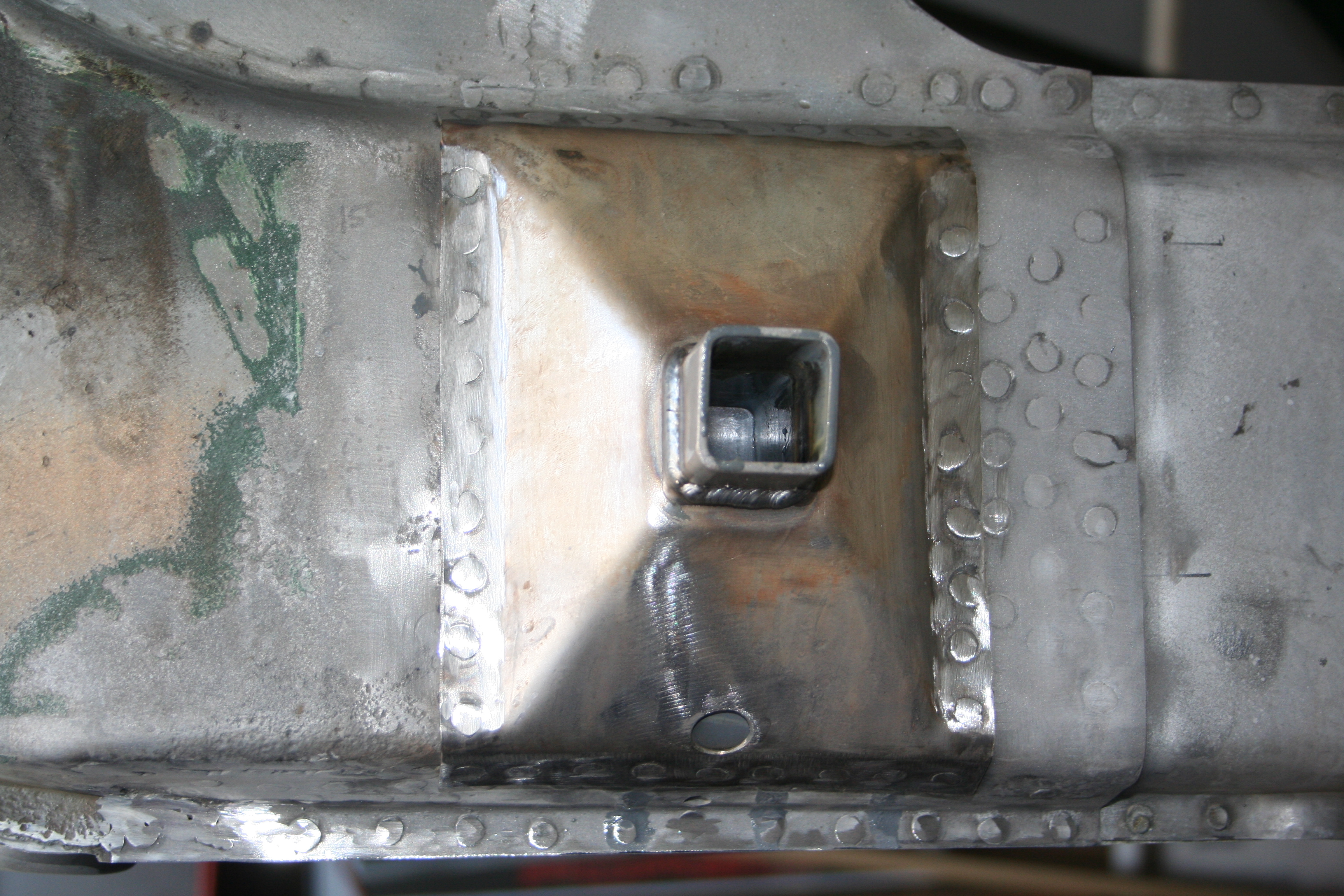
Checked the position with the pyramid in place. Here you can see the 135mm measurement.
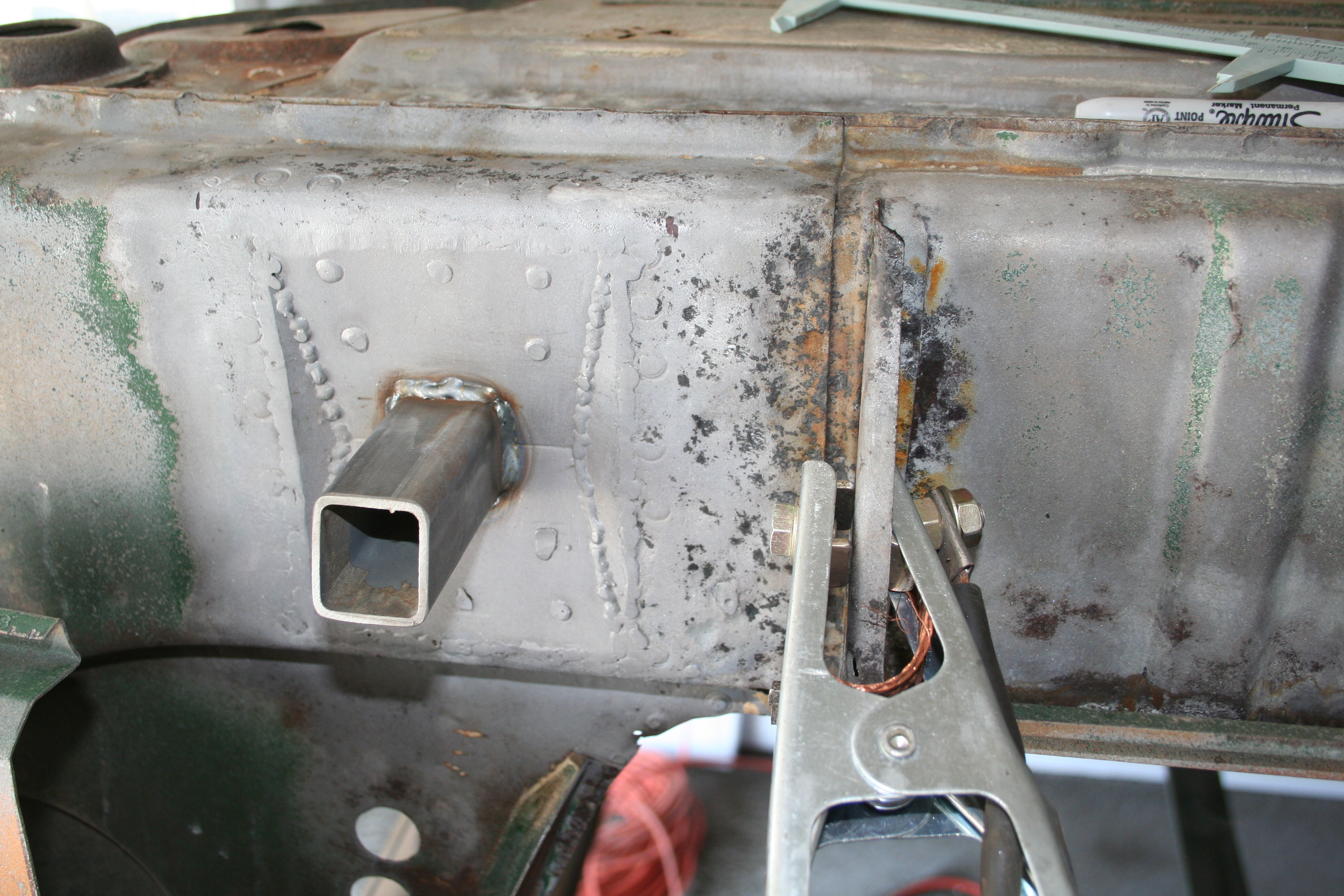
Now with the position confirmed, I do the final weld. I worked on both driver and passenger side at the same time, but the above is the driver side. Read more about driver side longitudinal repair work here
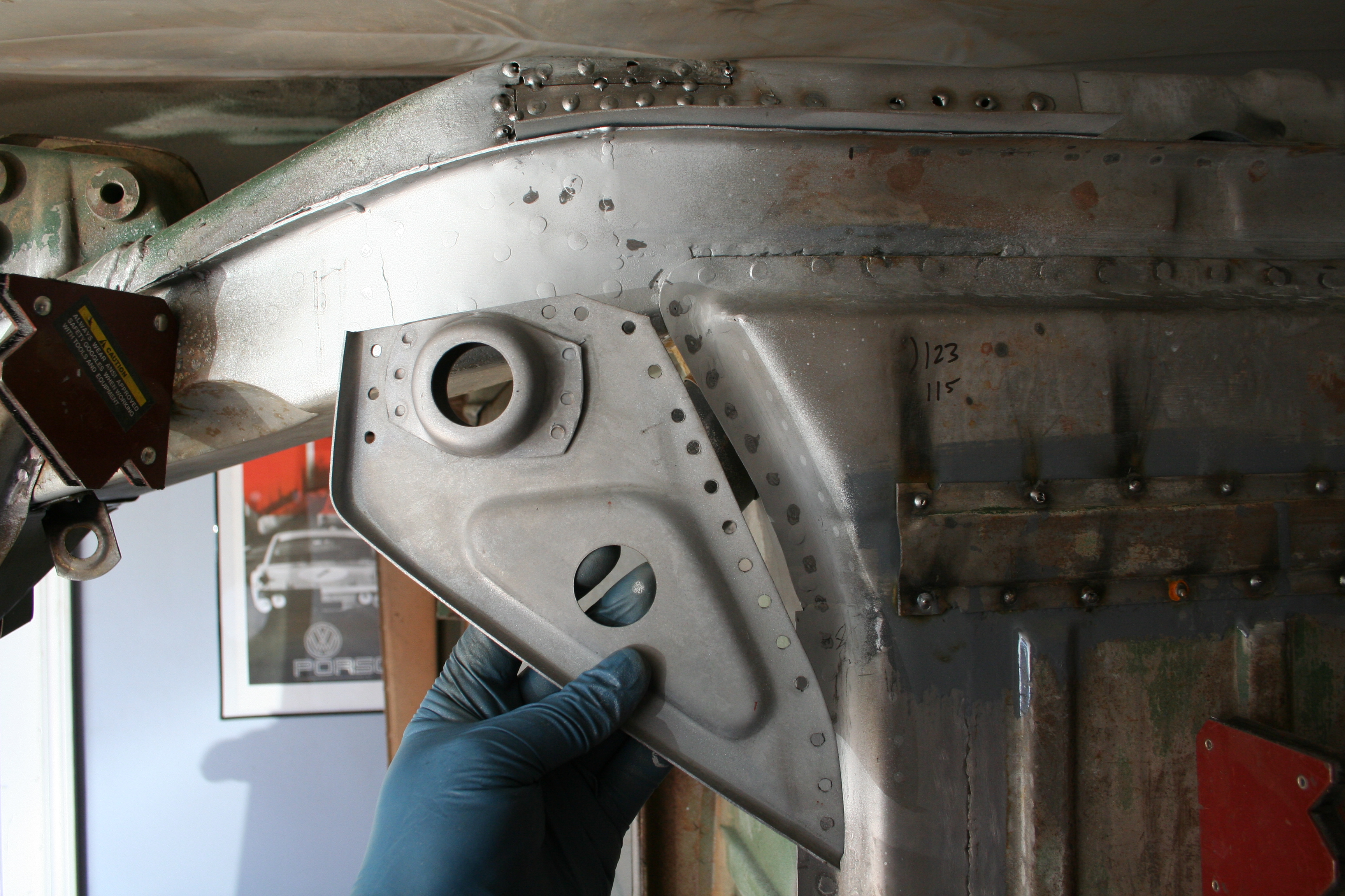
While welding in this general area, I decided to put in the triangular section that hosts the rear donut. I tried to measure the location of the good one on the driver side to get the correct position.
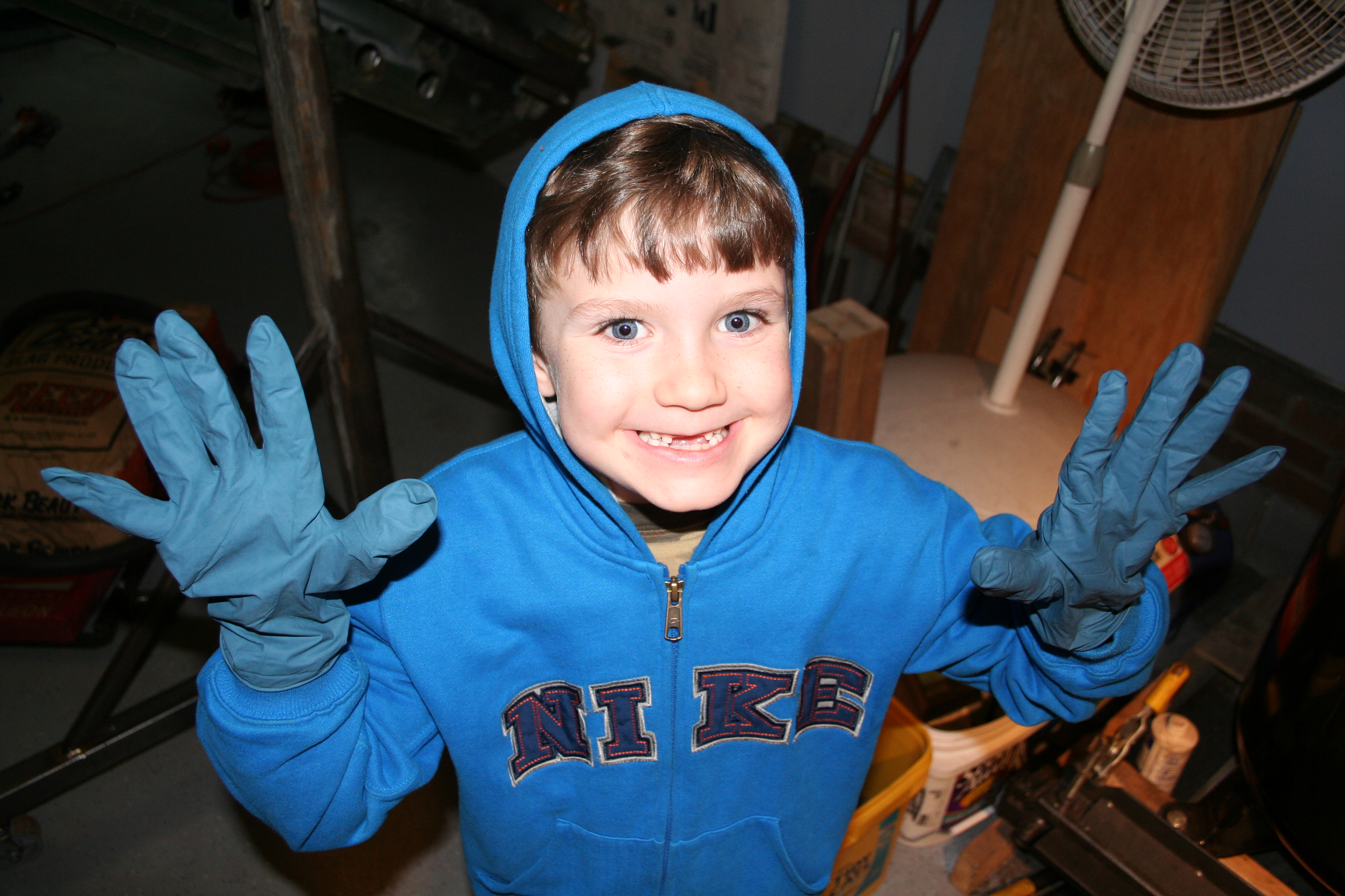
Donut in place. Read more about passenger side longitudinal repair work here 3/15/2009I was working on something else on the car, but Denver wanted to help so I figured he could help me take apart the rear suspension arm. The timing is not too bad as I am currently researching hub, stub axel, CV joint, drive shaft, transmission flange combinations for my 5-lug conversion. I also am doing some research on 911 e-brake setup
The blue monster is missing some front teeth! I also think the "one size fits all" gloves are a bit big.
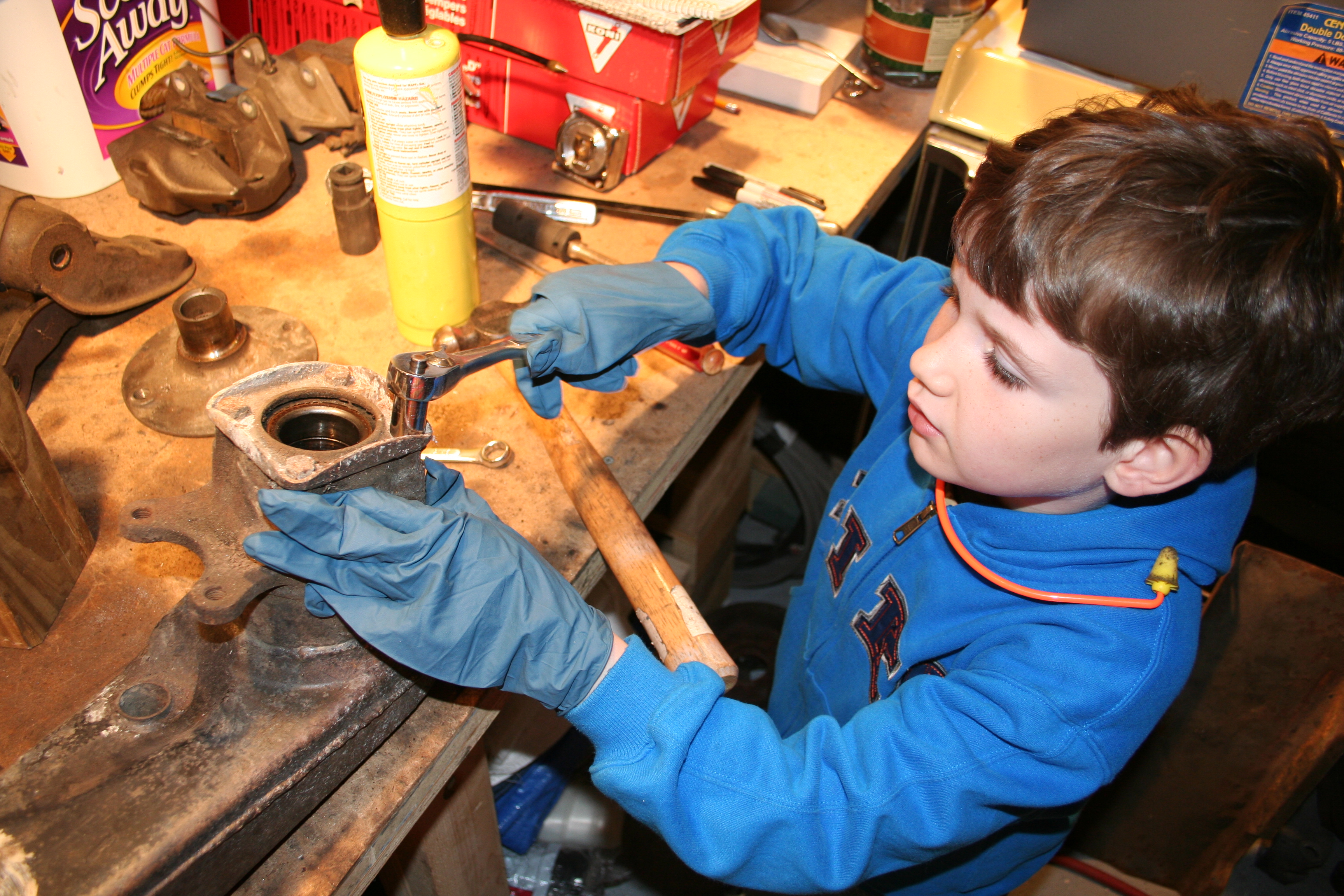
Ready to take apart.
Learning how to use a ratchet. He used the impact wrench for the first time a few minute early. Read more about rear suspension repair work here. I finished up the first/inner layer of the double wall and now am working on the second/outer layer. I actually had started forming this piece awhile back, but was unhappy with how it was turning out. So this is the second attempt. Here you can see the rough shape with two bends in it.
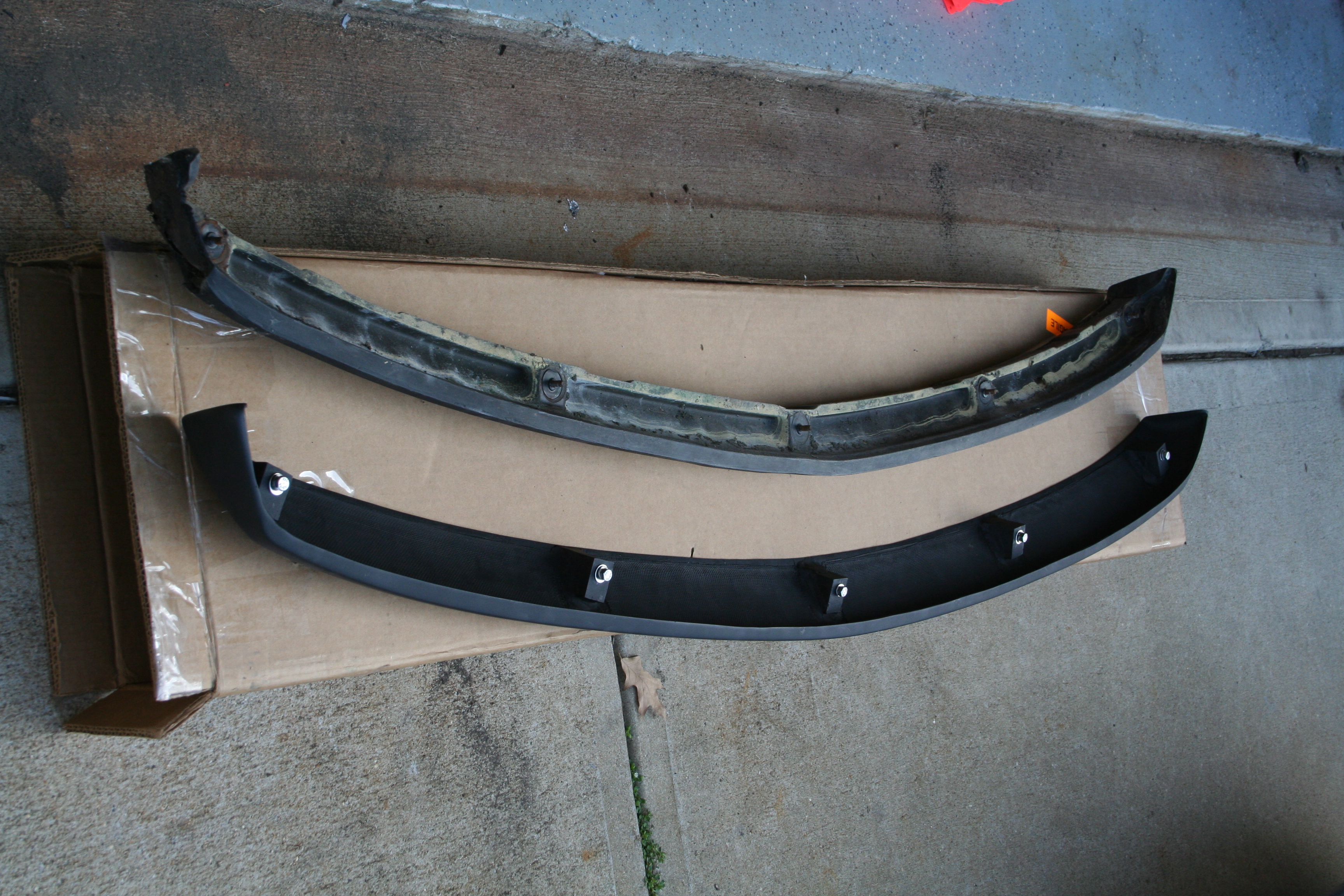
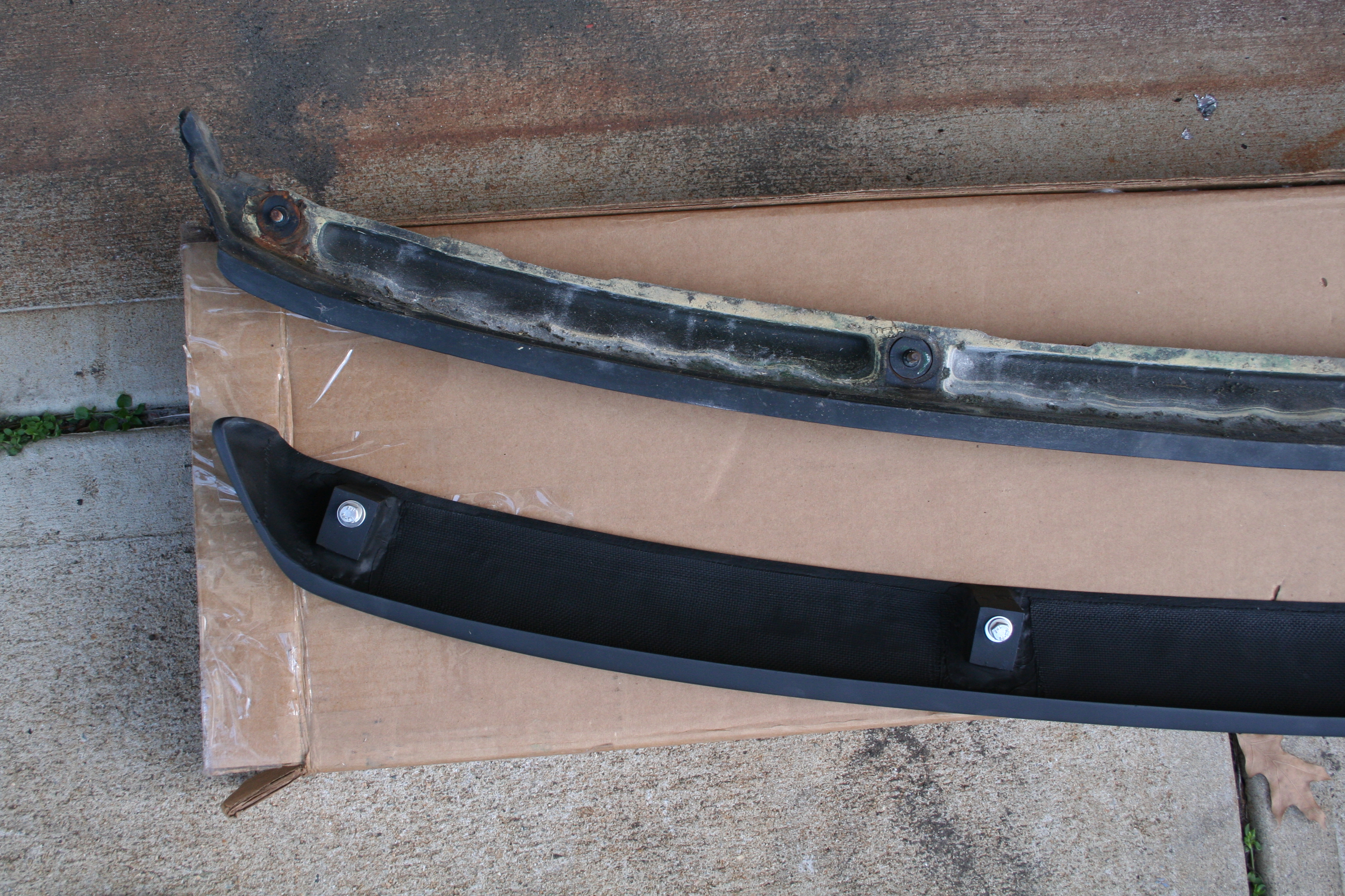
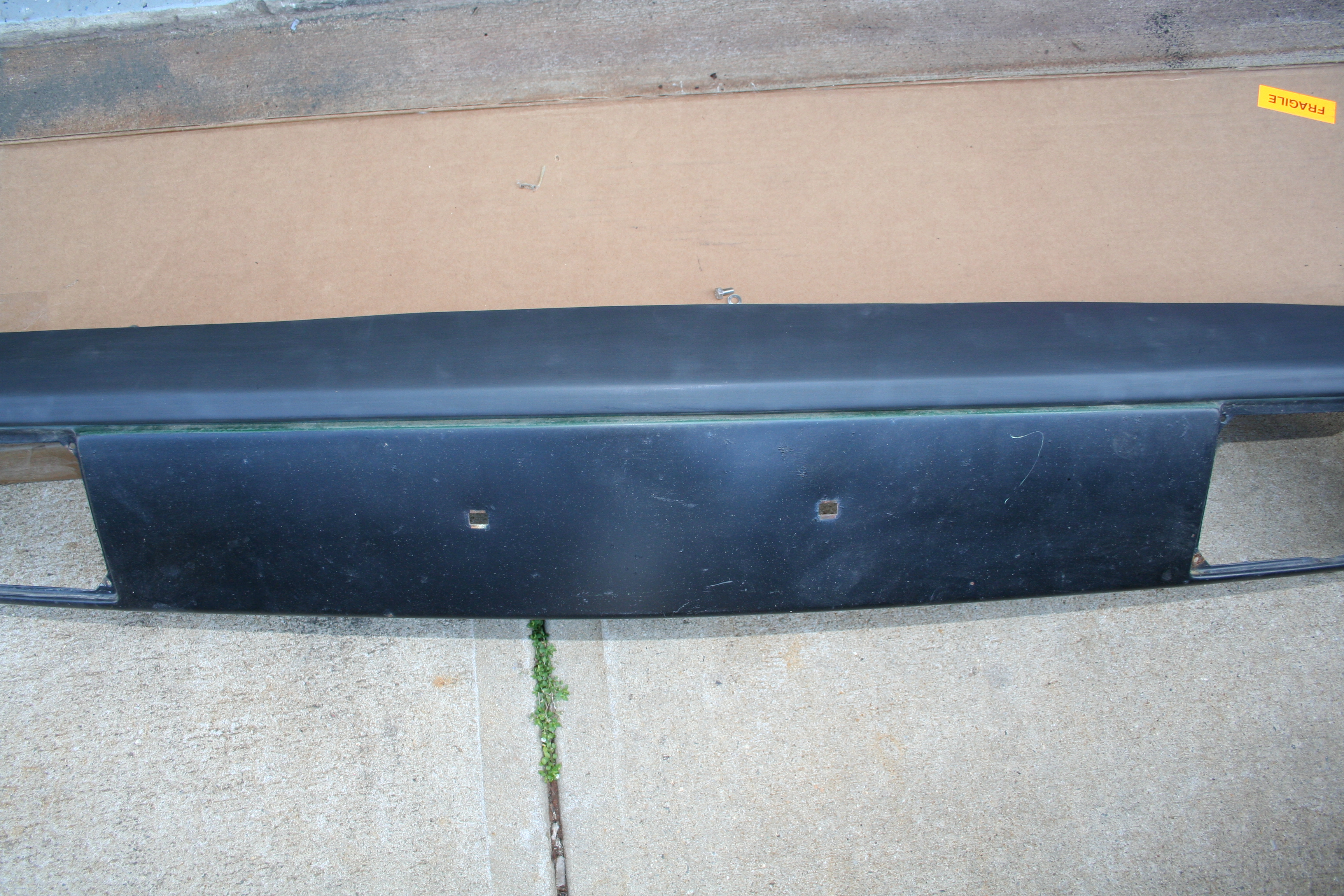
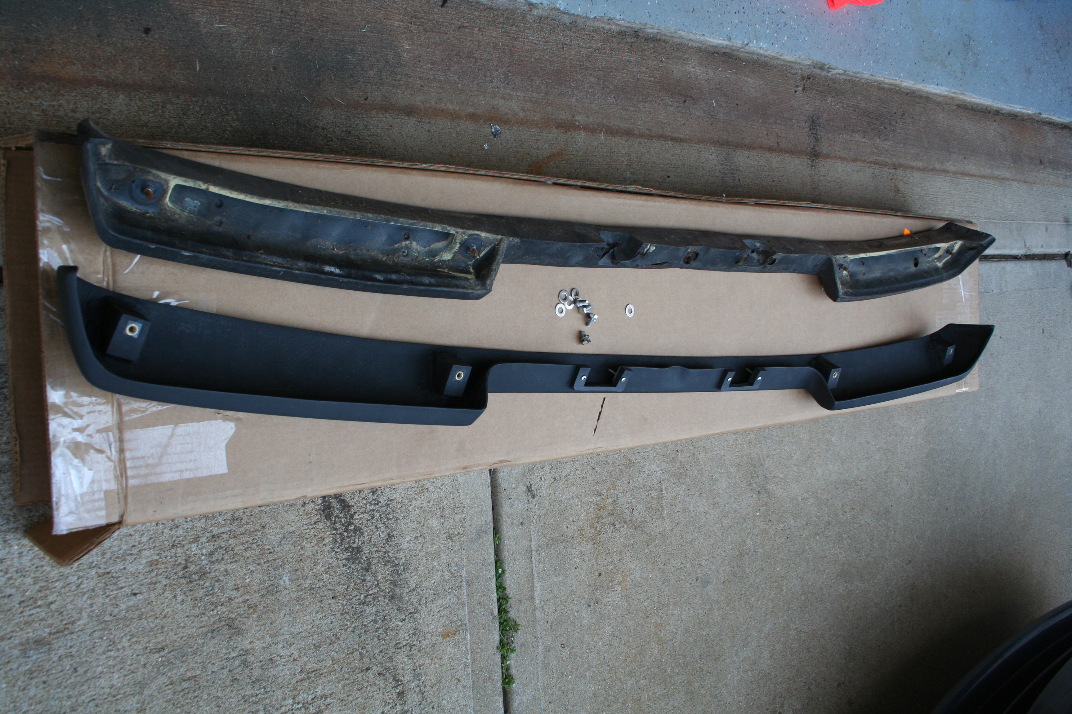
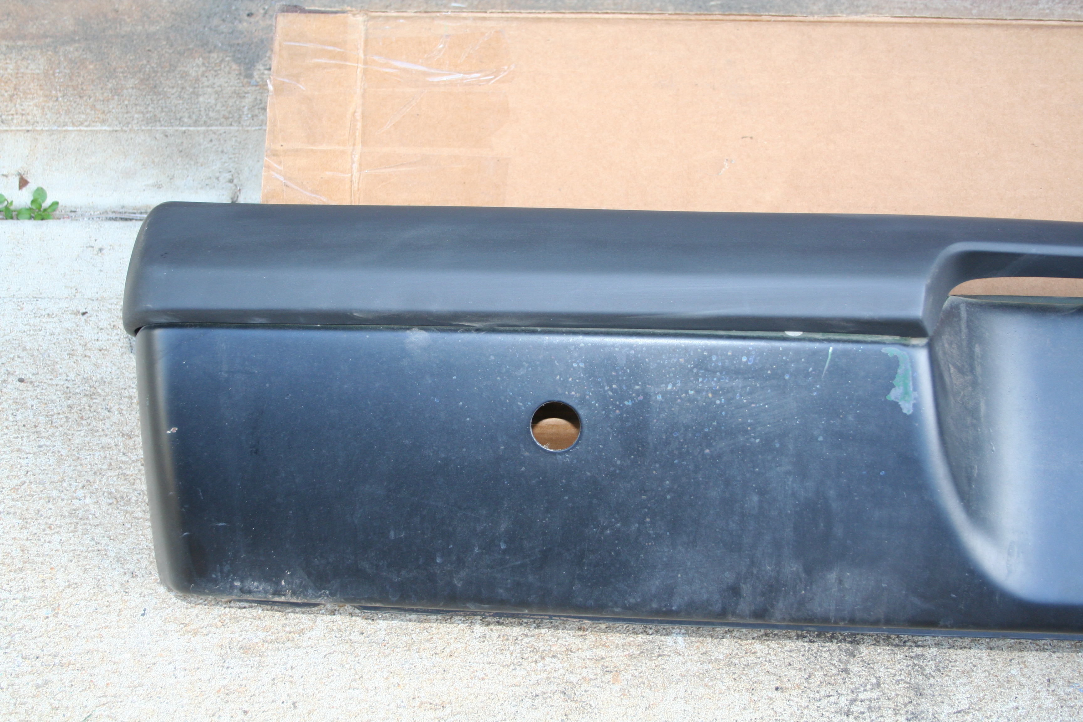
Working my way from the bottom to the top. Using a combination of metal brake and pounding over curved forms. Read more about passenger side longitudinal repair work here 3/7 - 3/8/2009I am going to test fit the fiberglass replacement bumper pads made by these folks... http://www.carlrudolph.com/ I bought the front/rear combo kit awhile back. They are much cheaper than the OEM pads and look very nice as well!
My old front compared to the new fiberglass replacement. Note the hardware is reversed. The OEM pad has stuts sticking out while the fiberglass has embedded nuts that you thread bolts into. The hardware is included with the fiberglass replacement.
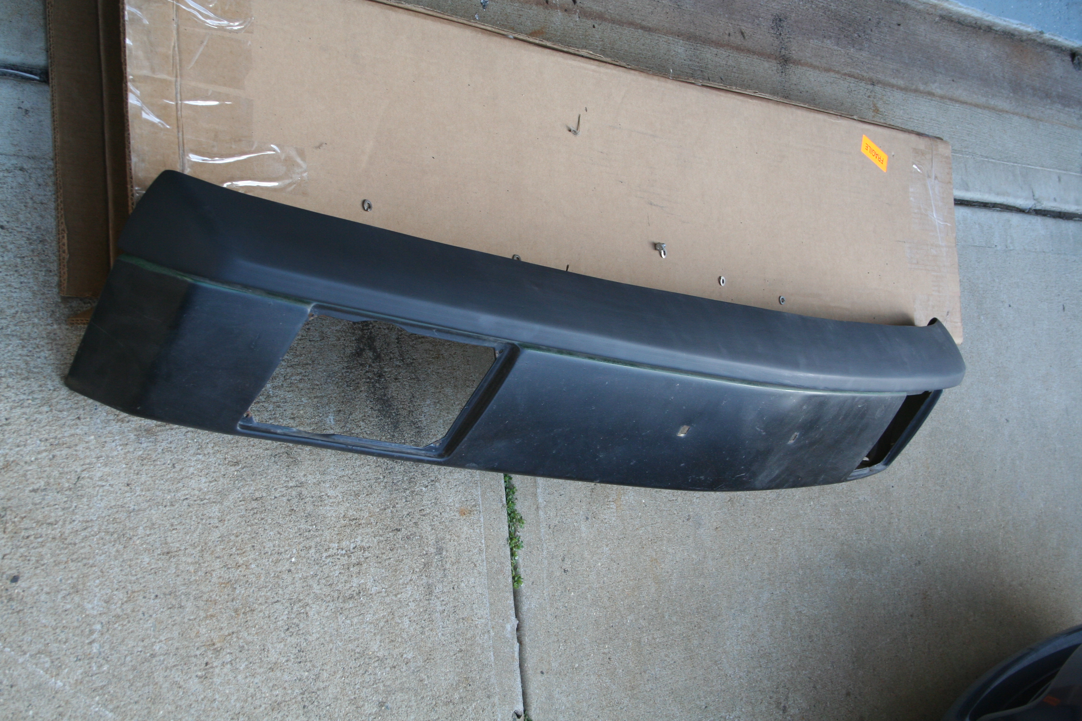
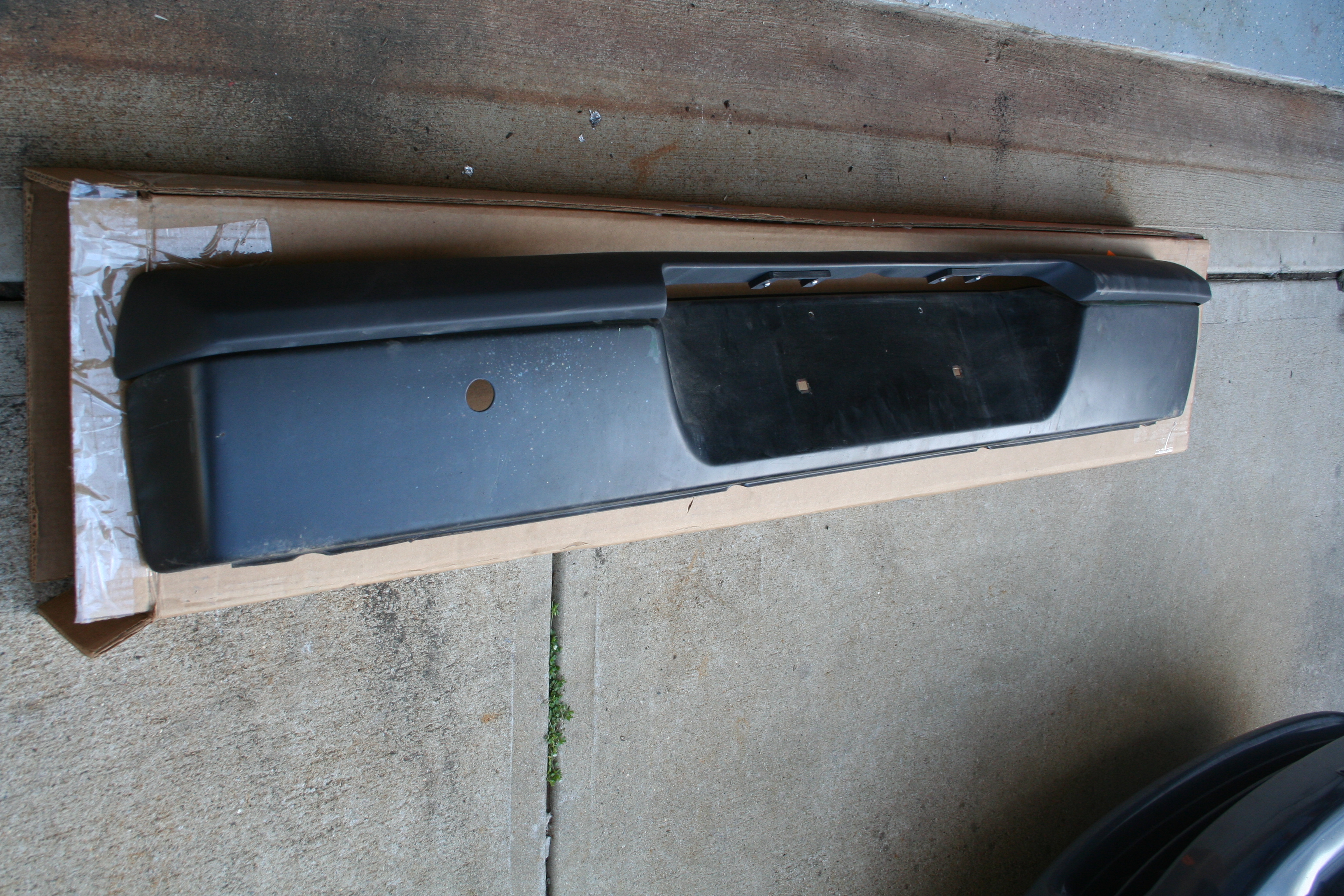
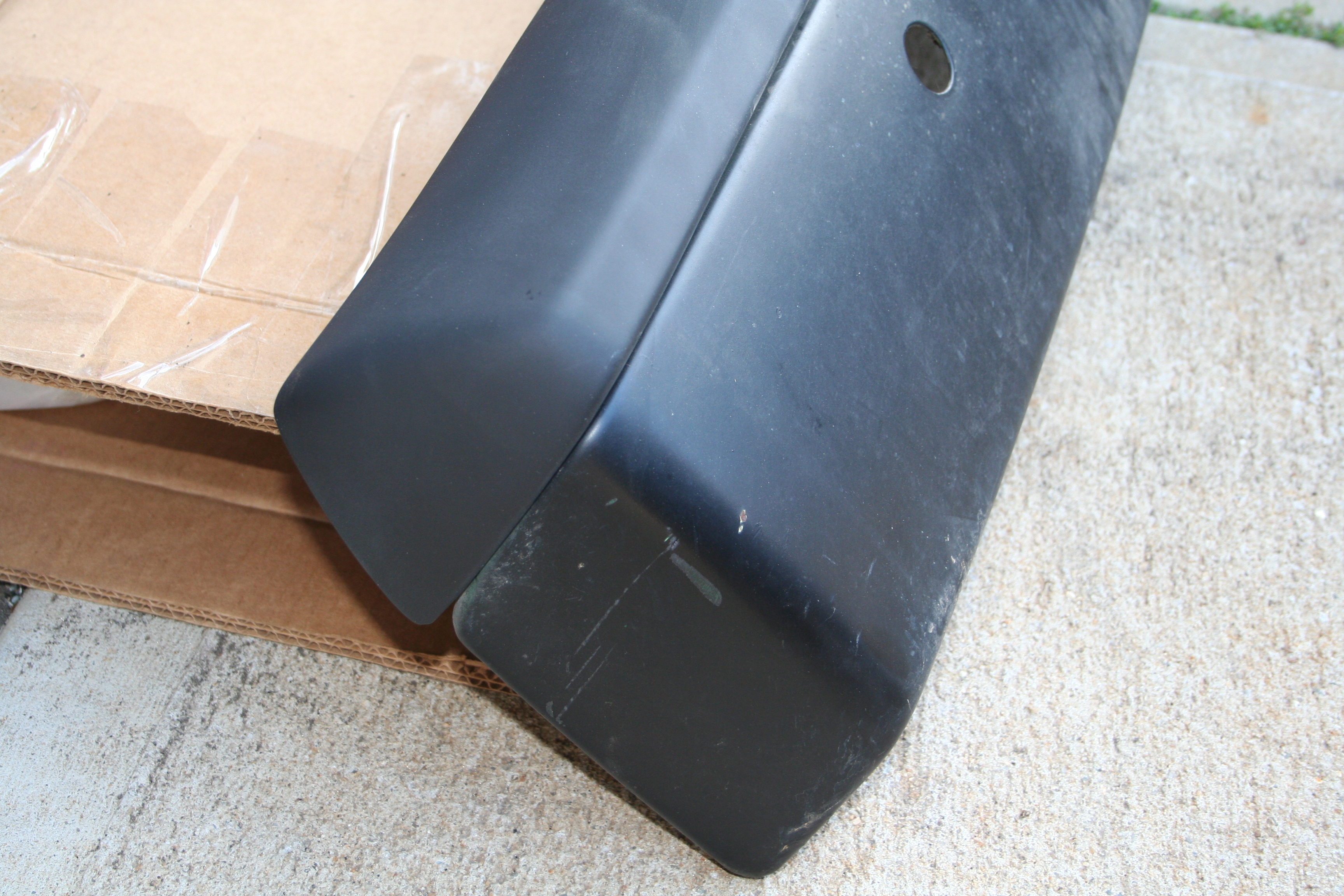
Test fit
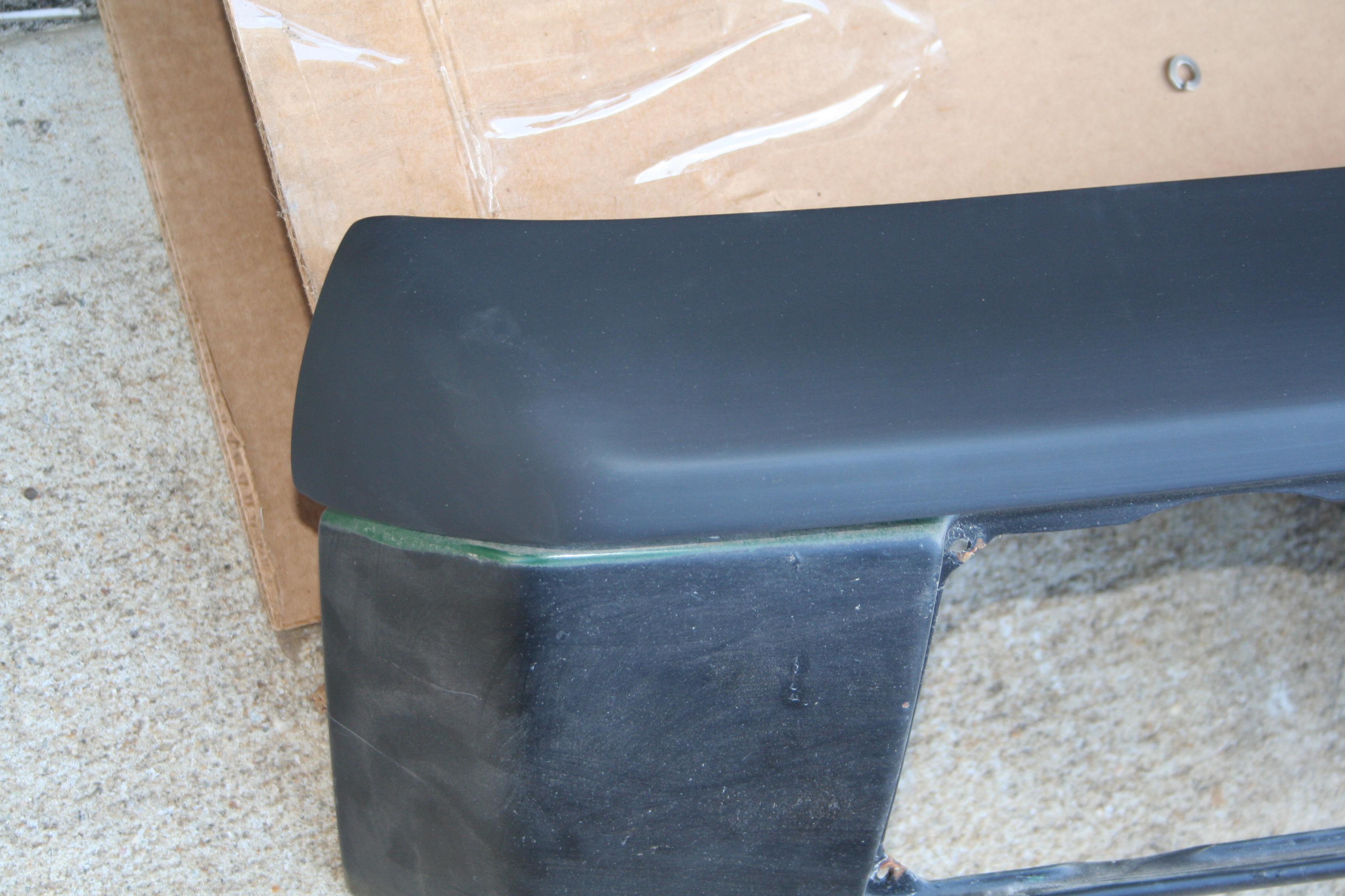
Closeup.
Straight and level.
Rear. Old vs. new
Close up.
Mounted.
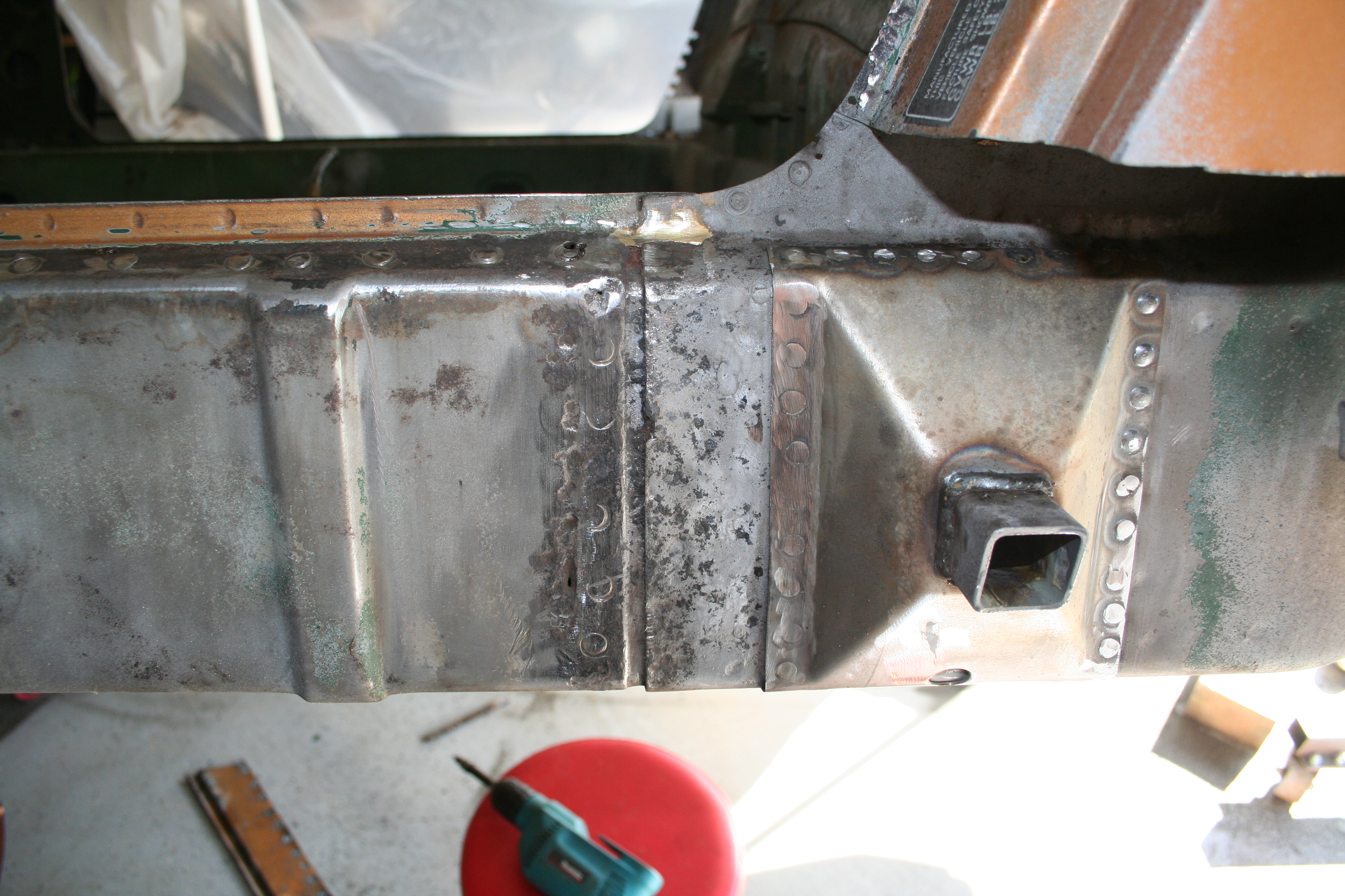
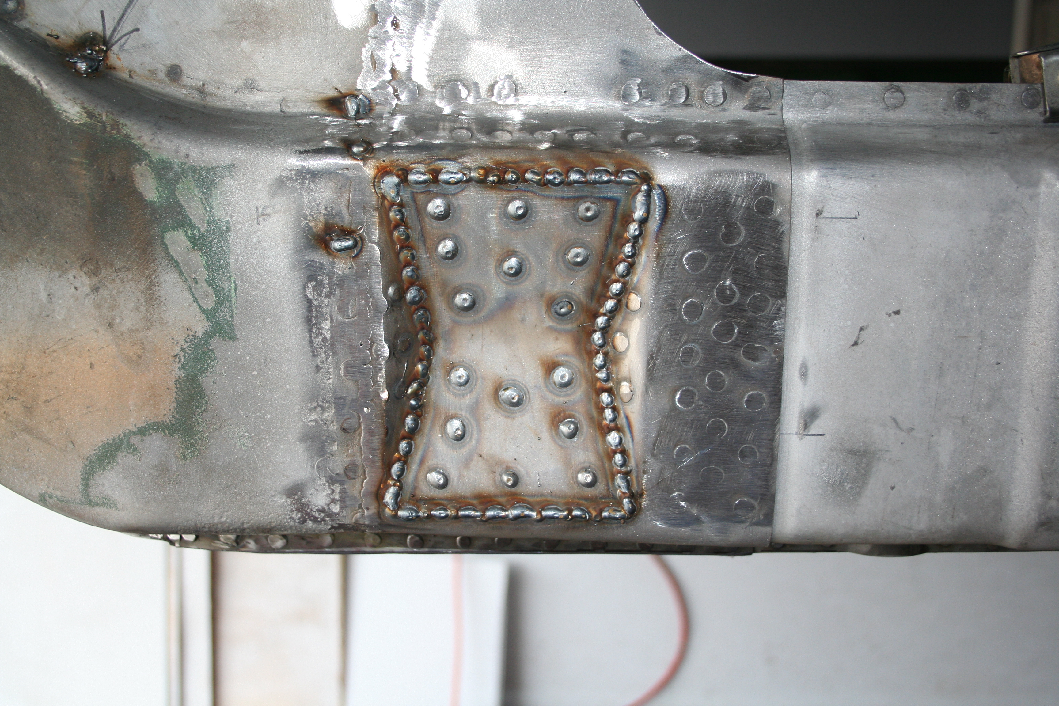
Looks good. 2/26/2009Now it's time to move onto the area right under the jack receiver pyramid. This is a double walled section with a 13mm recess. I believe that with the factory stamping, there is a small flat section where the receiver tube is welded to in this recess. It was going to be a pain in the ass to replicate that flat spot, but much easier to make it more of a reverse pyramid. This will require me to create a slight "V" shape to the tube, but this will only maybe be about 3mm and will only be slightly different from the factory stamping. But the first step is to fabricate and get in place the basic inner section of the double wall. Additionally there needs to be a notch in this to make room for the nut that is welded onto the final outer wall. The nut is needed because this is what holds the bolt at the bottom for the rocker panel. It is right below the receiver tube.
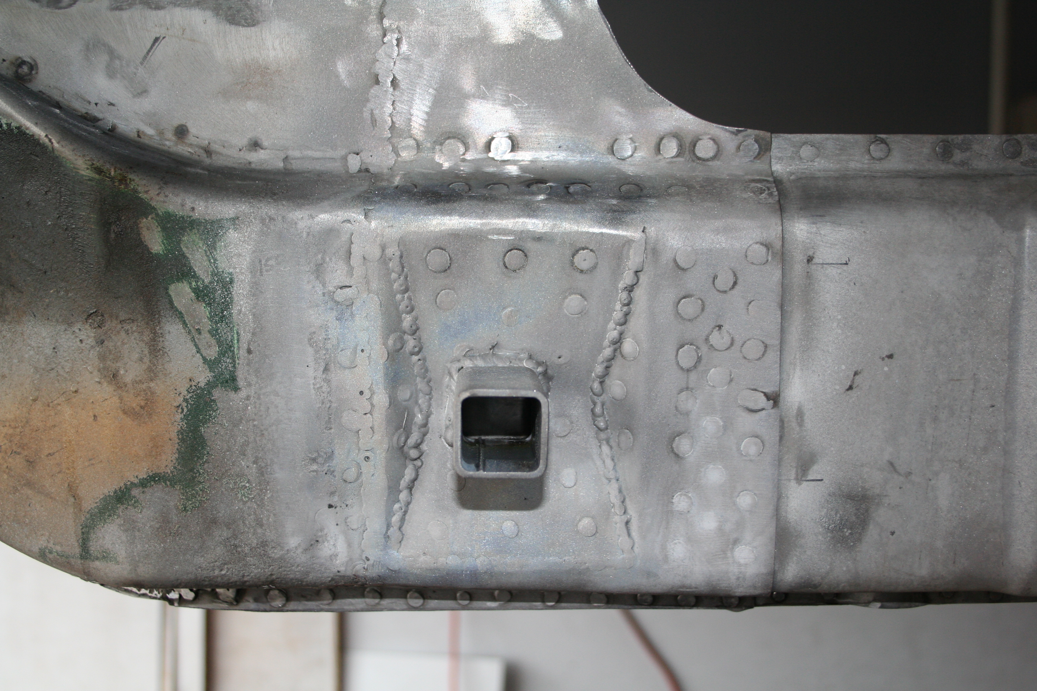
Clamped into place and ready to weld.
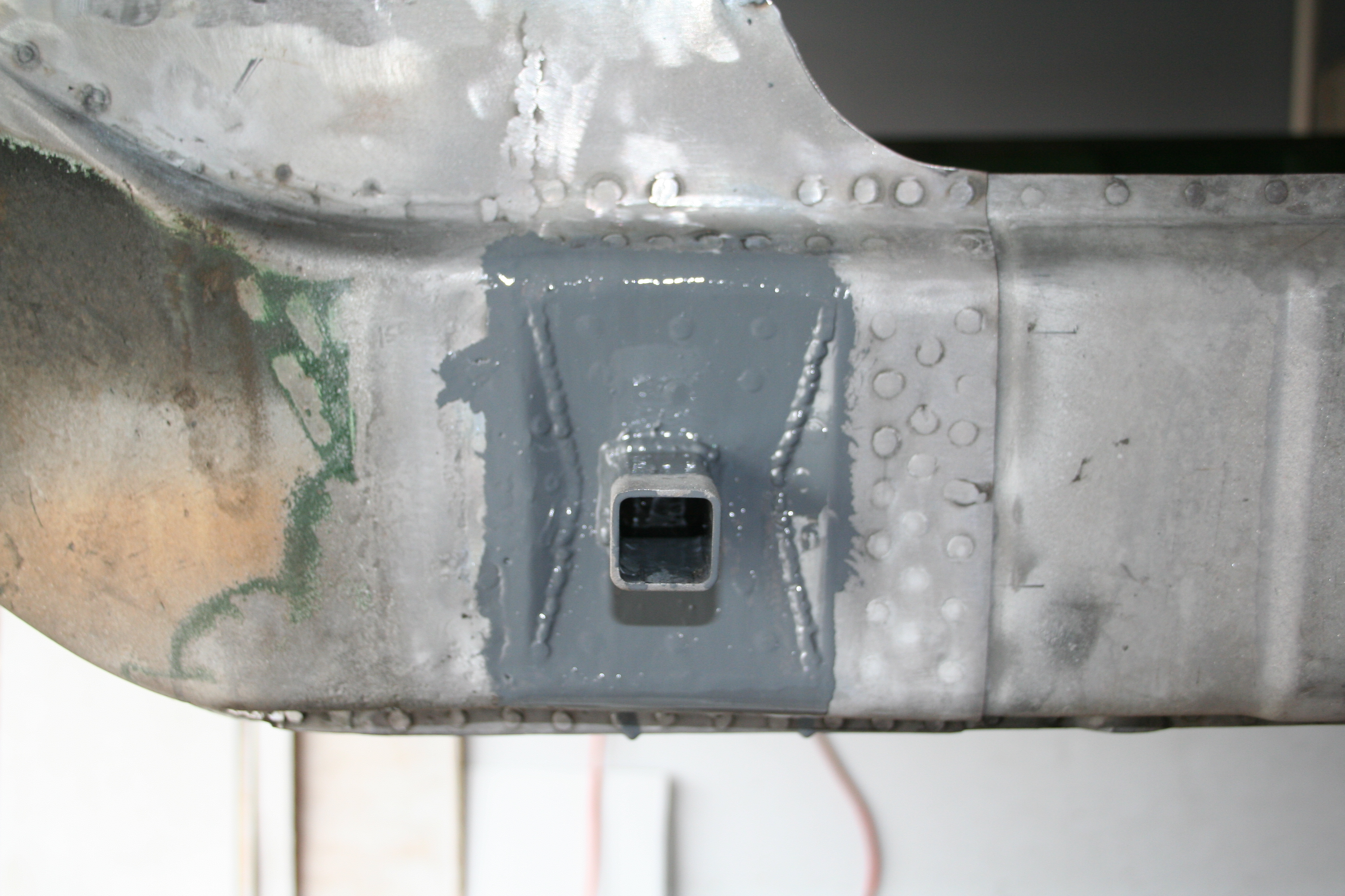
Once that is welded into place, then I can start the inner wall of the recess. This section has the 13mm recess.
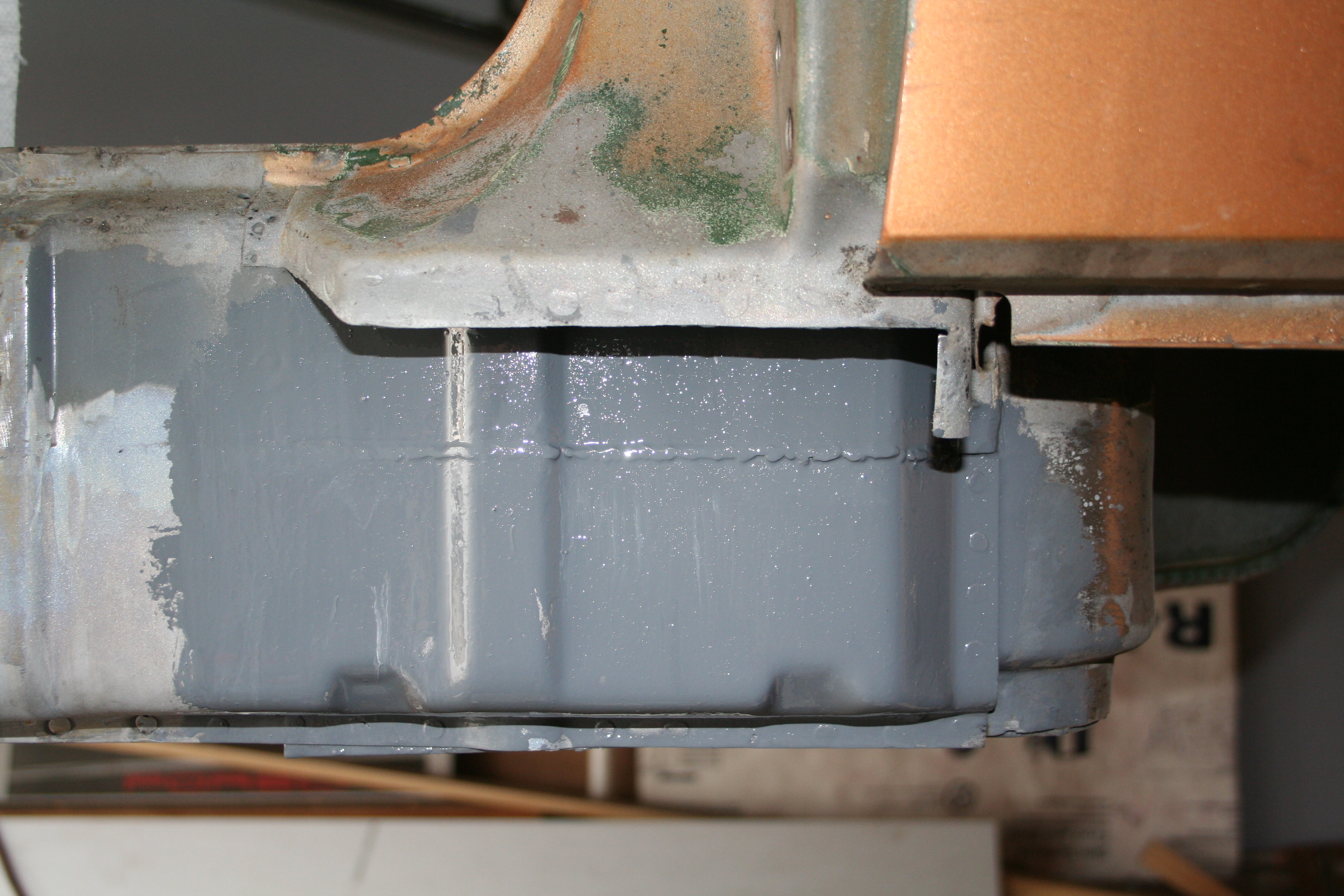
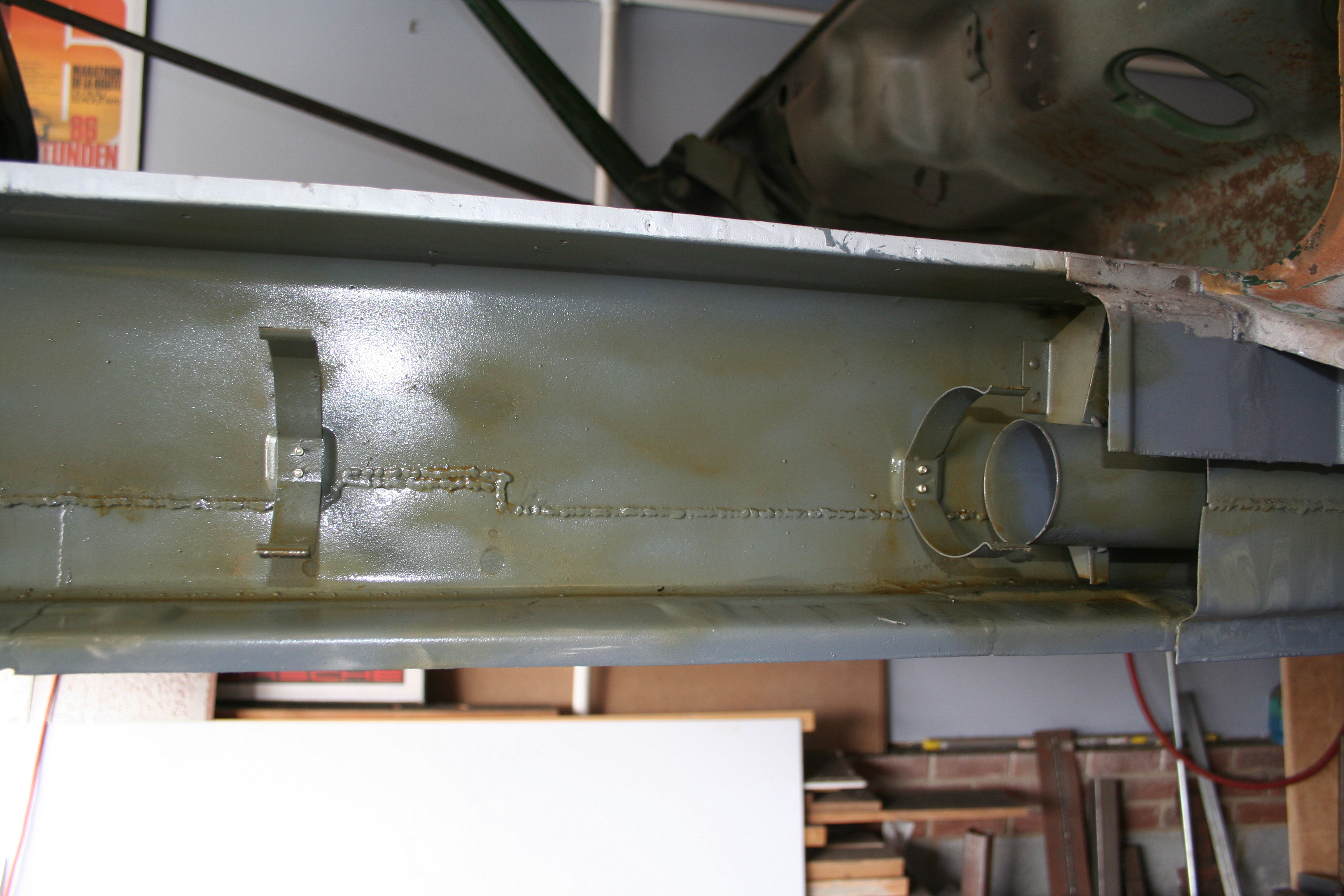
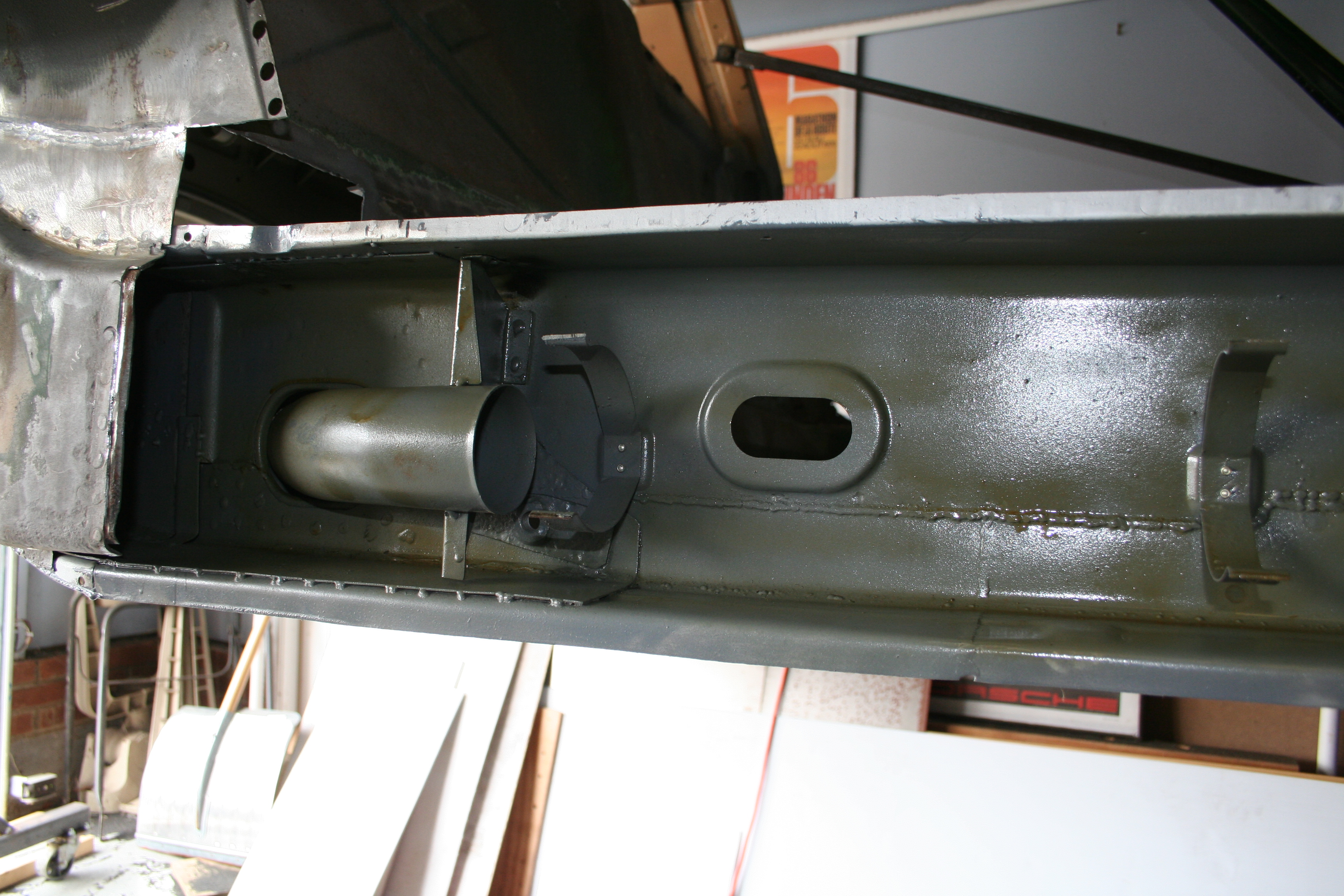
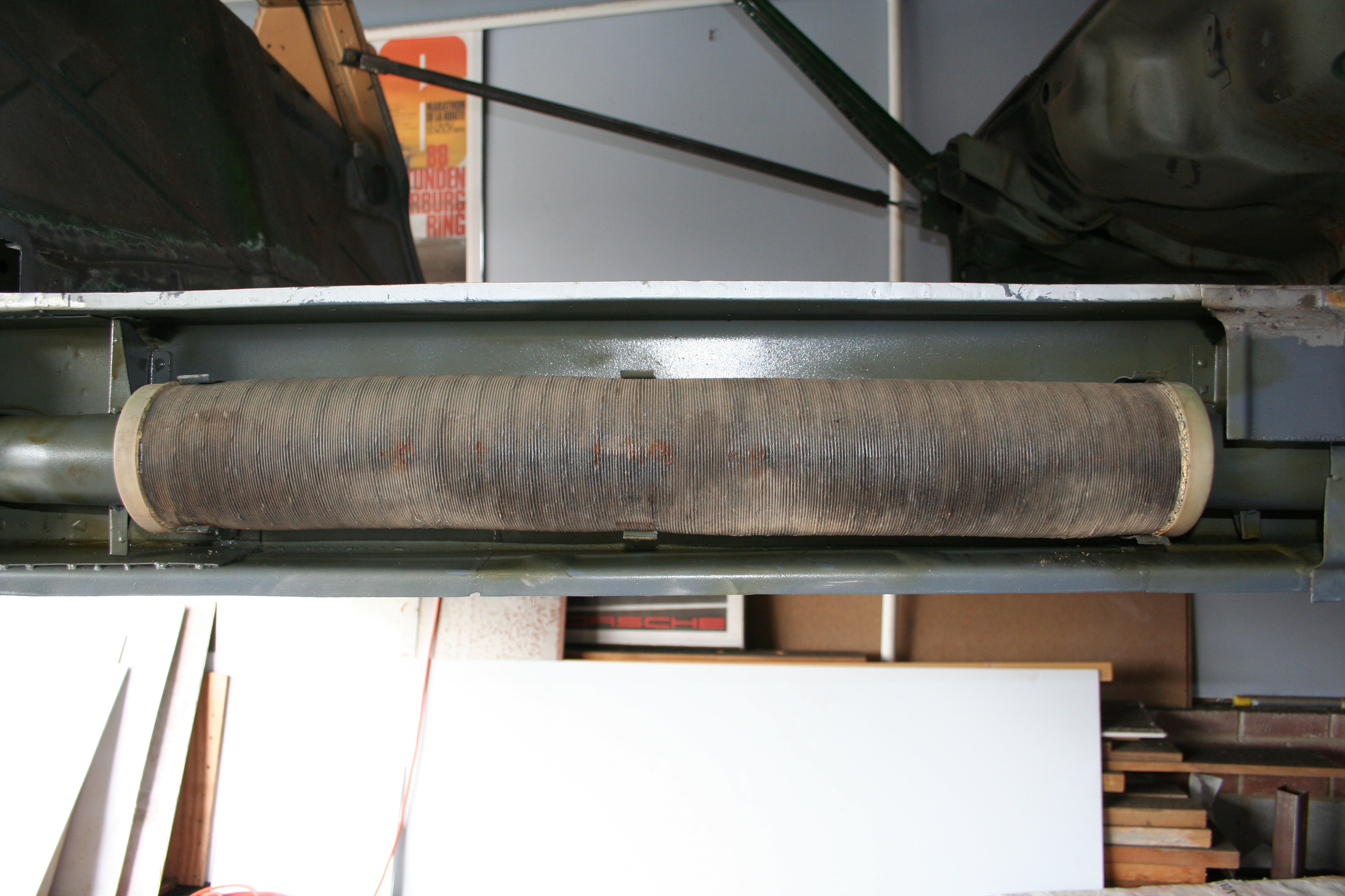
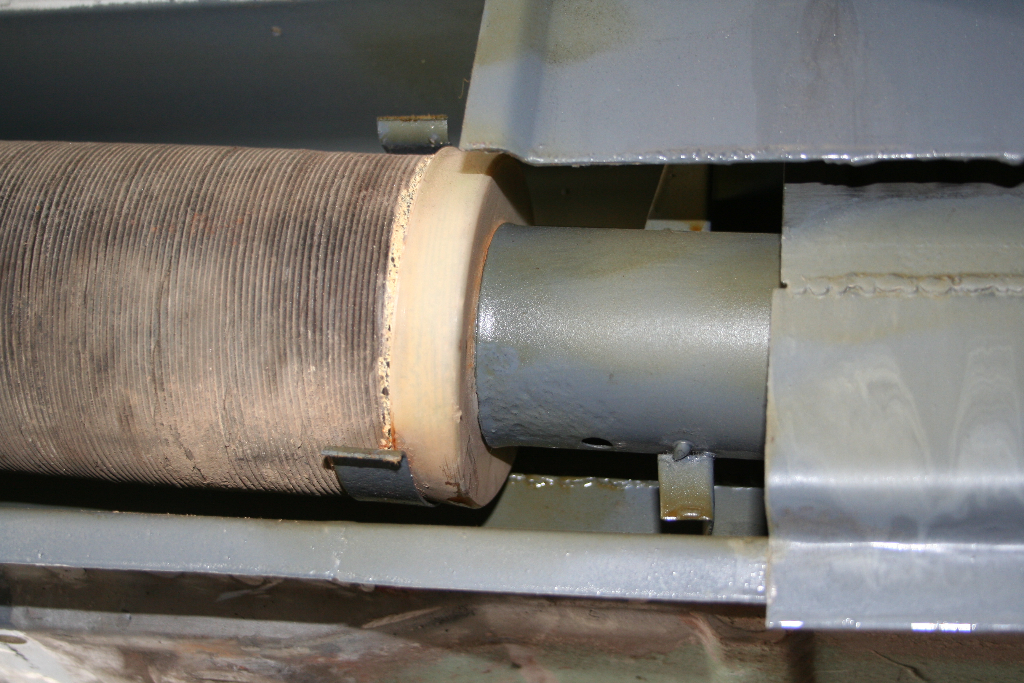
Mostly welded in place. I need to two smaller triangles to complete the reverse pyramid. Even then, this is just the inner wall. Read more about passenger side longitudinal repair work here 2/15/2009Ok, I am finally ready to weld on the outer clam shell onto the longitudinal. I had riveted in the three clamps for the heater tube and painted the inside of the outer shell a few days ago. Then today, I sprayed the interior with my CRC anti corrosion spray (wax). That is what the yellow/green stuff is. Then I put back in the heater tube in place and then welded the outer clam shell into place. I double checked the gap at the top of the car (no change due to the braces that are holding the upper car in place. I then worked on making sure that the clam shell was positioned correctly by using some long straight edges. Clamped all of this in place with many vice grips and then welded it up.
Spray on wax
Tube in place. It fits pretty snug and it was rotated back into the exact position as it was when I removed it.
Seam weld started
Seam weld finished, but not ground down yet.
Rosette "spot" welds are looking good.
I was very excited to get this done. It went very quickly. Read more about passenger side longitudinal repair work here 2/13/2009Fabricated and welded in this small section. I replicated the small "half moon" indent in this section.
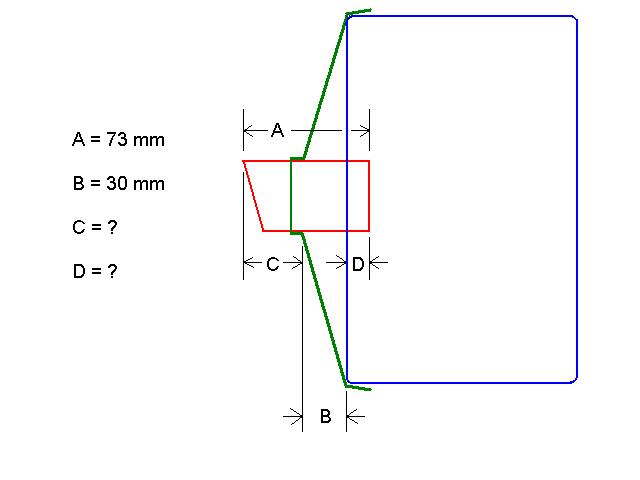
Read more about passenger side longitudinal repair work here 2/8/2009I am working on putting the jack receiver tube and pyramid back in place and would like to do this on both sides at the same time so that they will be identical. Additionally there is more evidence remaining on the driver side as to the exact location (front to rear) of the pyramid. Basically the previous owner had ground off the bulk of the pyramid and the first layer of skin under it, but the edges remain and this allows me to measure it's exact location. One thing that I don't have is the depth of the outer skin under the pyramid. Basically there is an indentation under the pyramid that the receiver tube is recessed into. I want to replicate this depth correctly because it will allow the tube length to be correct and at the same time not stick out beyond the edge of the rocker (once those are installed). I started this 914world.com forum thread to get some info as to what the dimensions are for an unmolested factory jack receiver tube and pyramid are. I had some dimensions, but not enough to determine how deep to recess the tube. Here is the diagram from that thread...
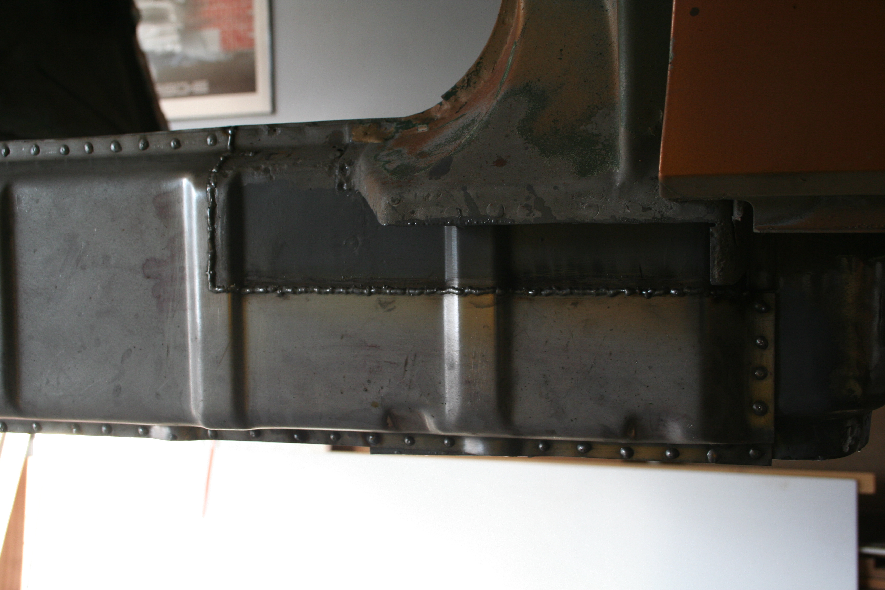
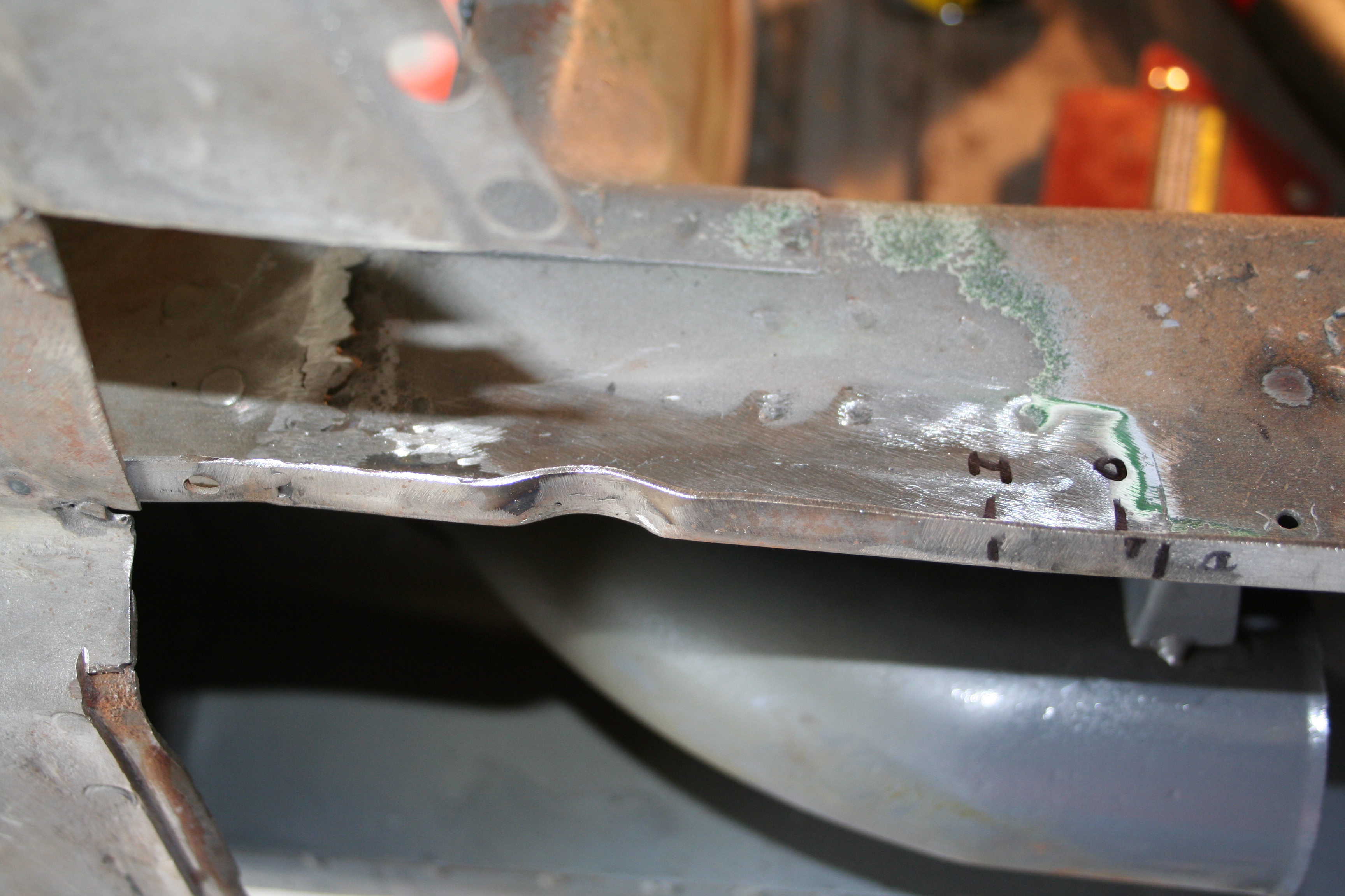
As it turns out, C = 30 mm, so D = 13mm. So the recess needed to be 13 mm. I apologize as the photos look upside down. That is because the driver side in my garage is against the wall, so it was just easier to rotate the car on the rotisserie so that it was closer to my work area, but upside down. The the photos are upside right, but the car is upside down.
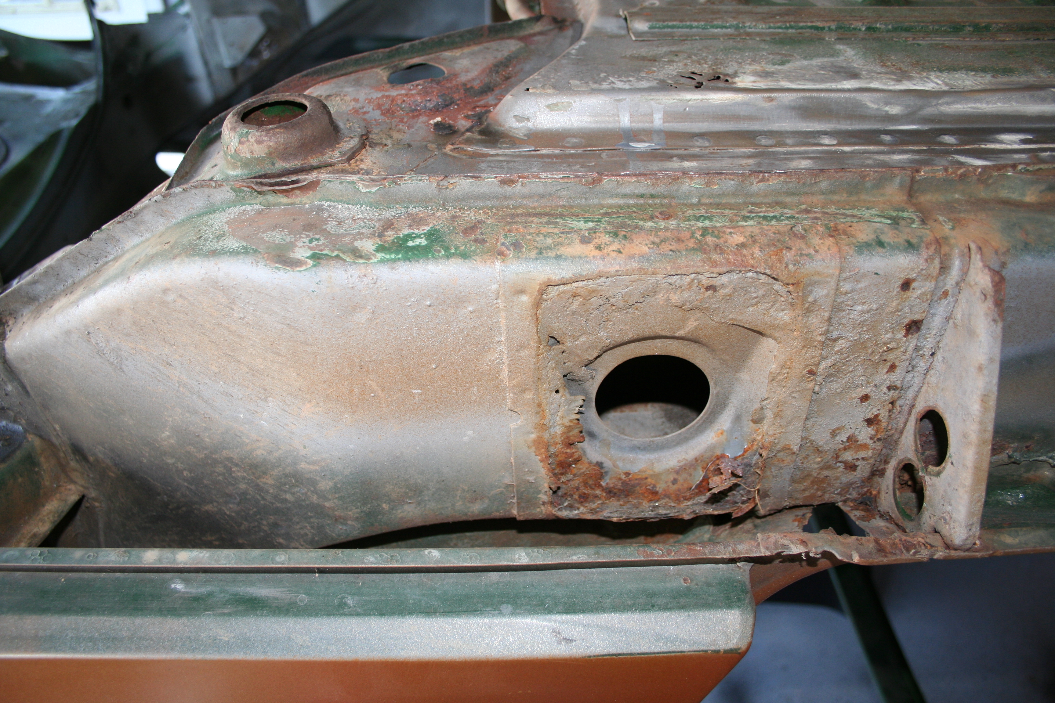
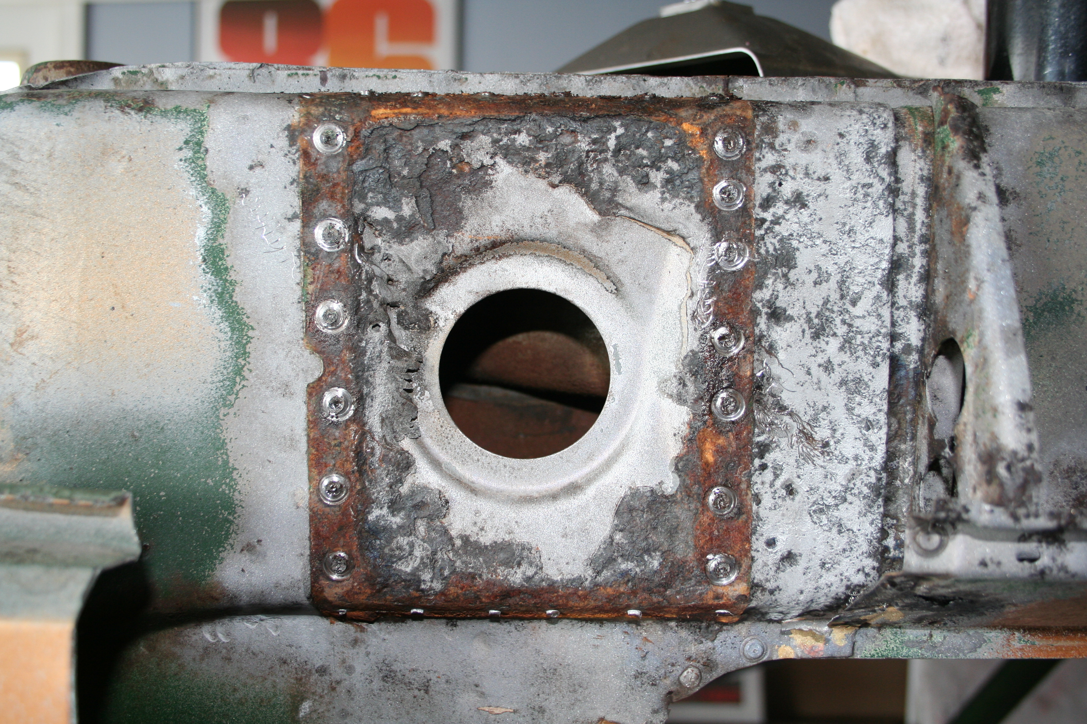
As left by the previous owner. You can see the pyramid is mostly gone as well as the outside skin of the longitudinal. This weakens this area as well as exposes the hold in the inner double wall.
More of the longitudinal. It is solid on the driver side.
More of the same.
I will deal with this rust later. I also expect that I am going to need to remove the "sill" on the driver side just like I did on the passenger side.
More stuff to deal with later.
More of the sill.
Another small hole to fix later.
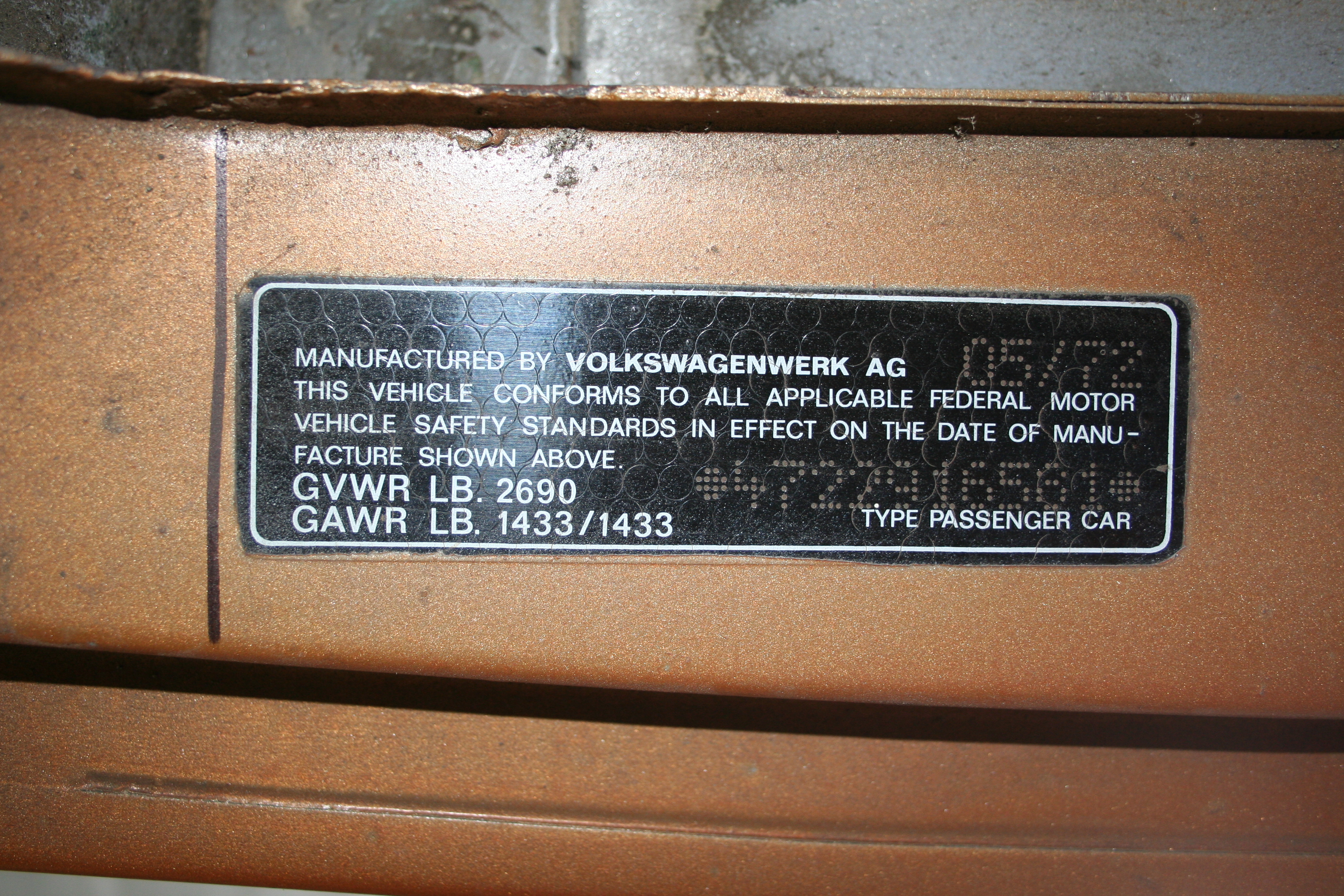
I expect the DOT sticker is not going to survive all of the repair work.
Just like the passenger side, I have cut a bit of the fender away to get at this area. I know some people repair this without cutting the fender, but it sure is easier with a section of the fender removed. I have also done a first pass at media blasting as well as treating with Ospho. The black sections is rust the is not flakey, but is also very hard. Because it's very hard, it's also very hard to remove via media blasting.
More of the problem area on the front. I think that once the sill is remove this should not be too hard to repair.
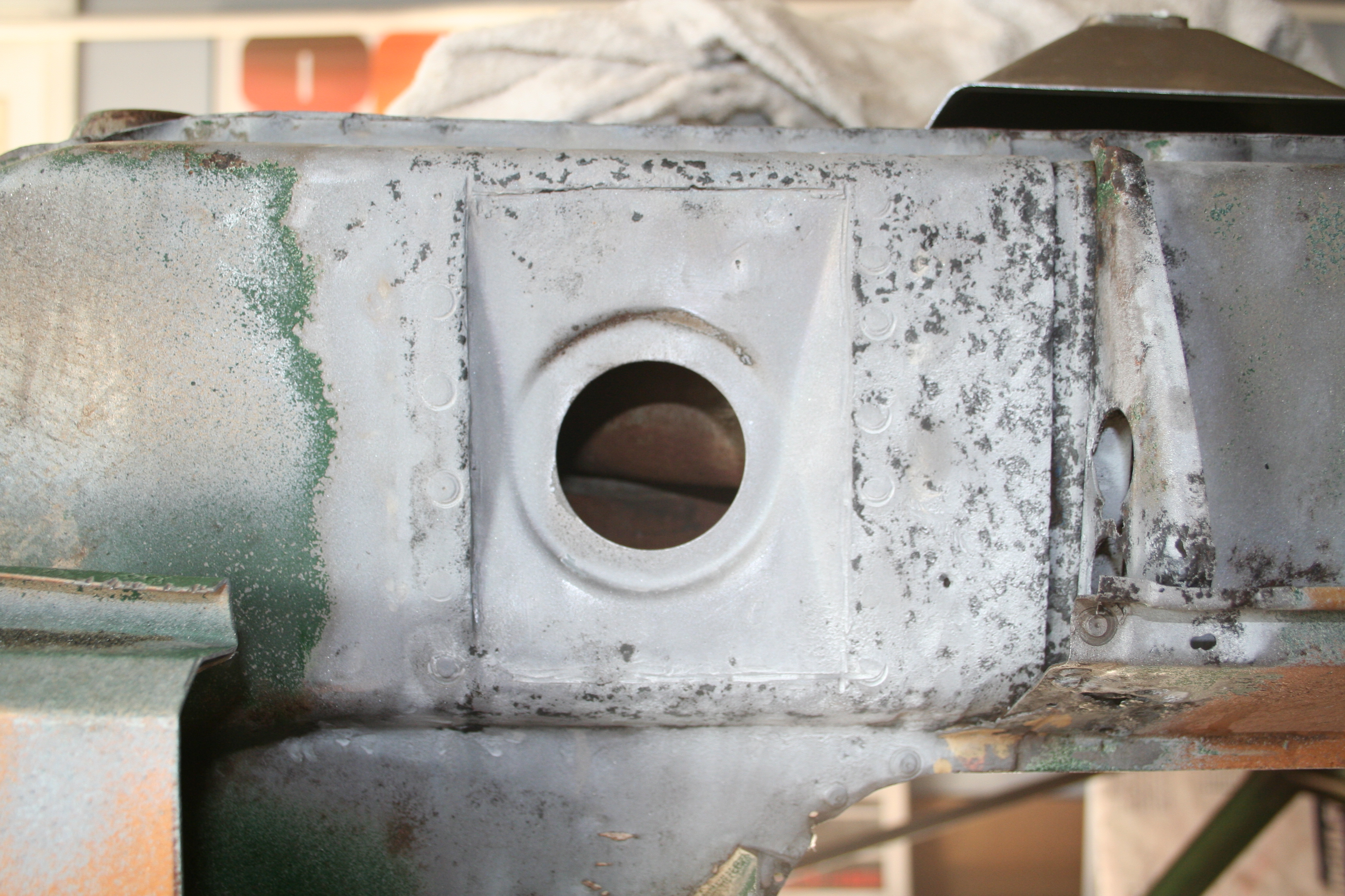
After measuring the exact location front to rear, I drilled out the remaining spot welds and removed the last bit of the pyramid.
Move media blasting to remove as much of the last traces of rust.
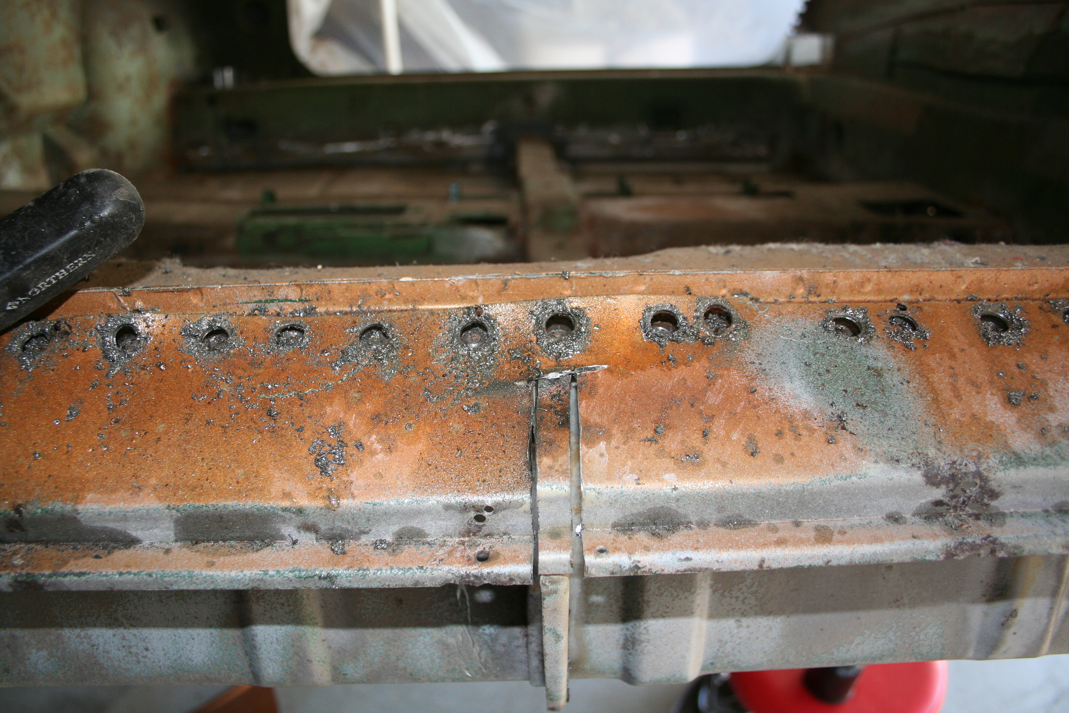
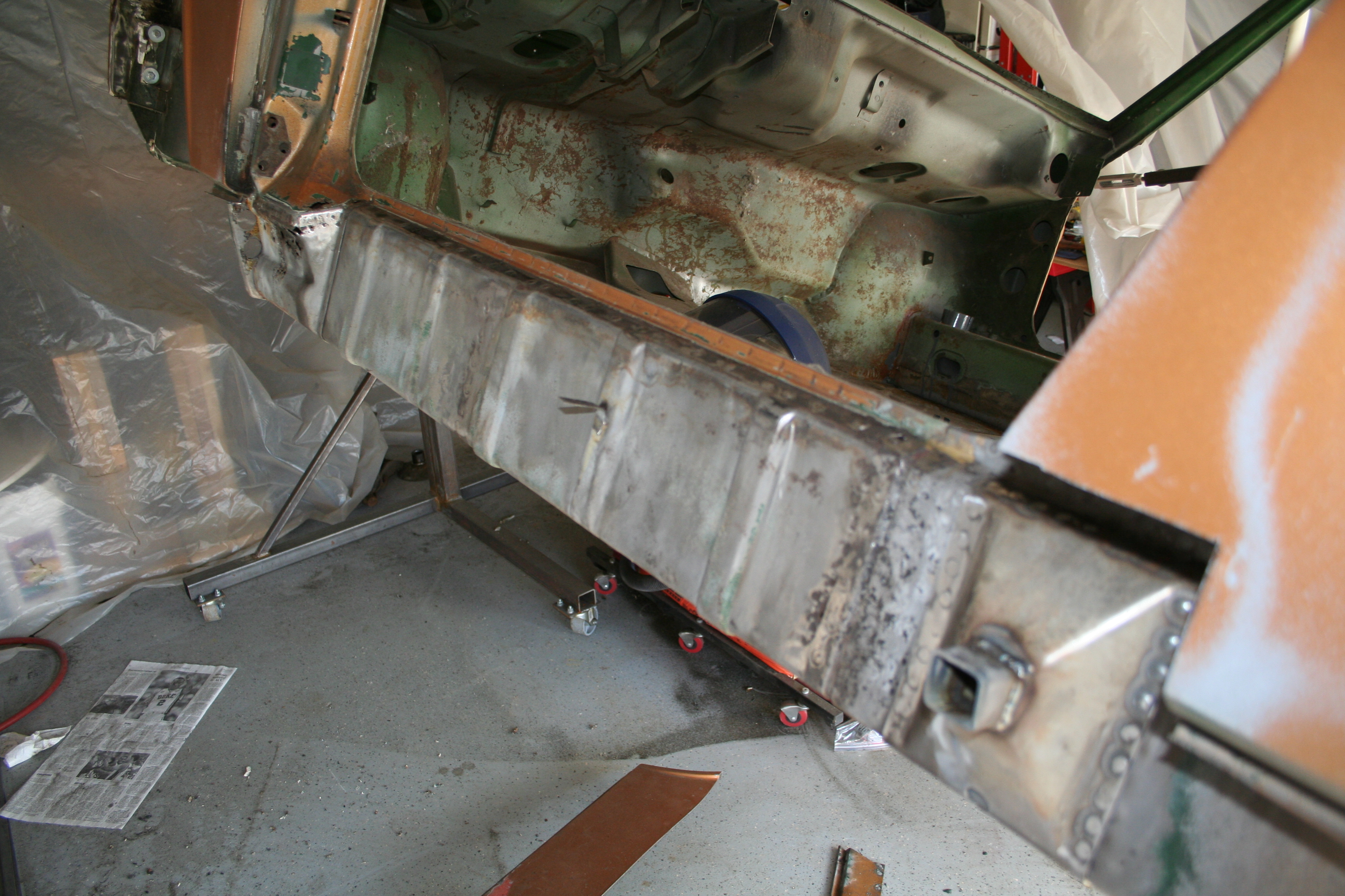
Upside down. Read more about driver side longitudinal repair work here 1/19/2008Now, I need to focus on replacing the last section of the crossmember. I have the original (rusted beyond repair) so I measured it and am fabricating a replacement.
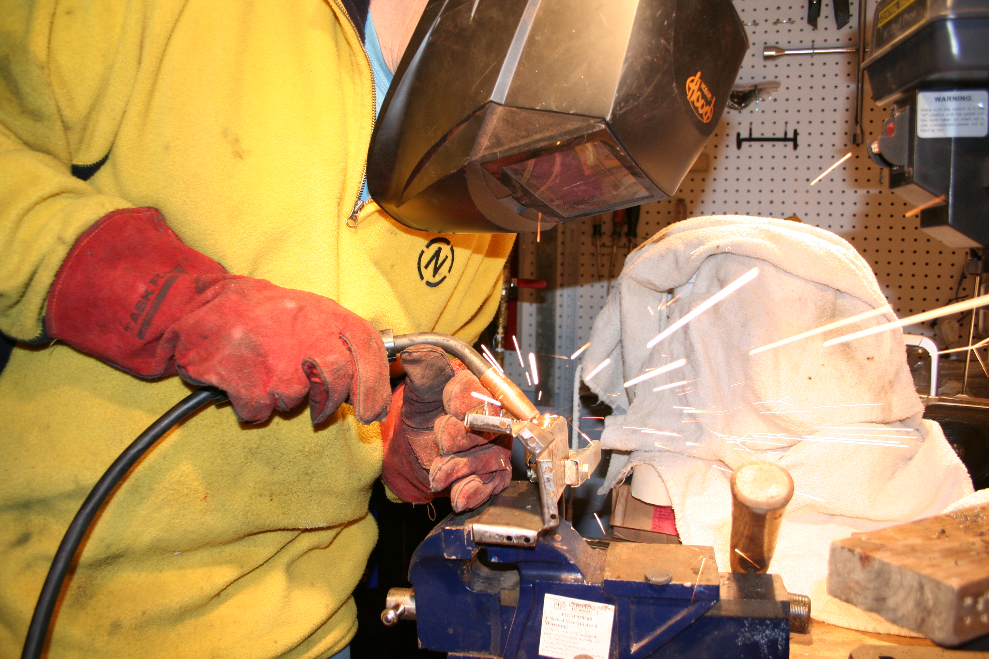
Another action shot. Here I am welding up the replacement section. So... what is wrong with this photo? I am wearing welding mask, and gloves, so what is wrong with my welding protection? I am wearing a synthetic fleece jacket. Hot molten balls will burn right through it. I need to buy me a leather welding apron.
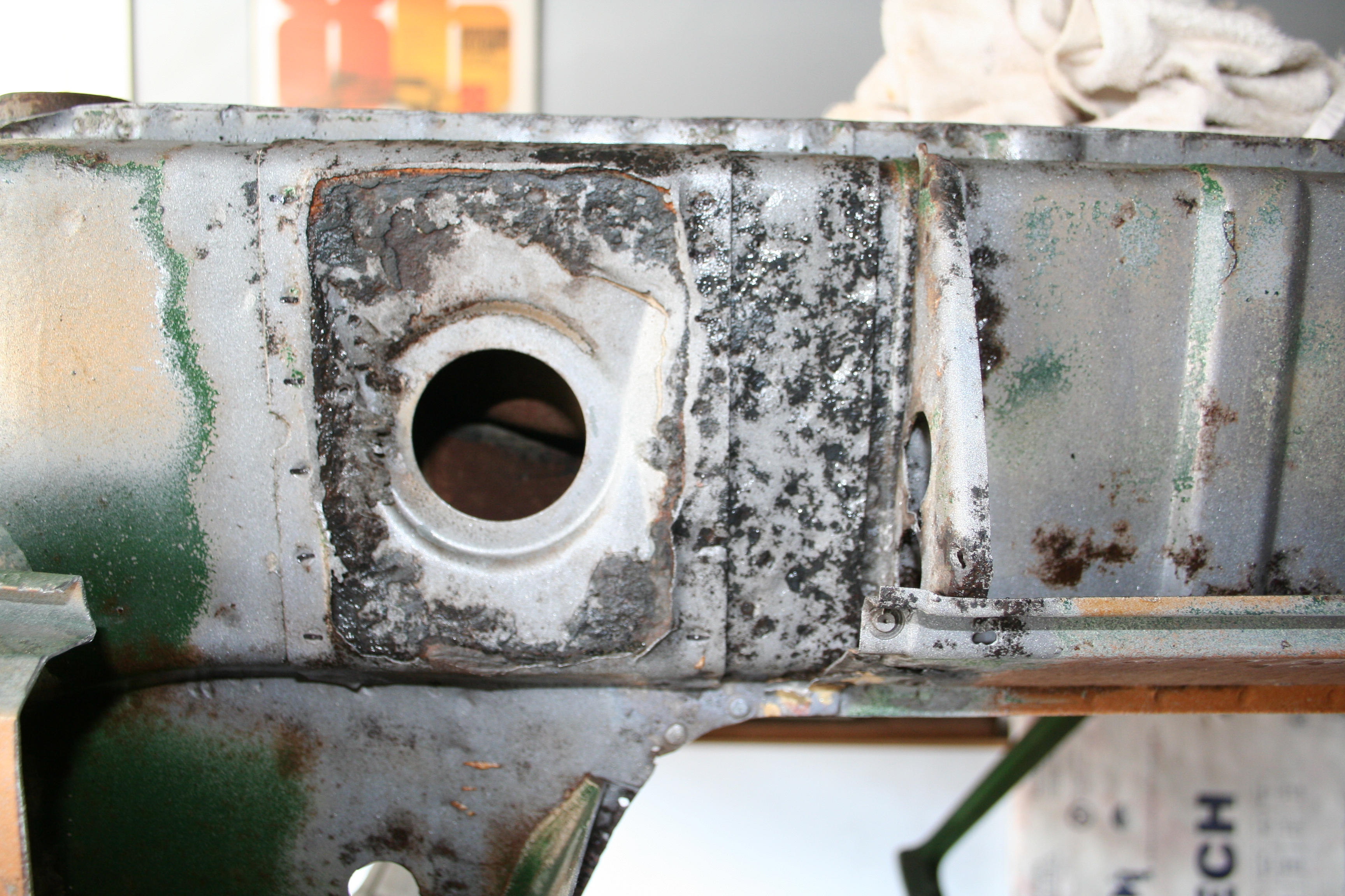
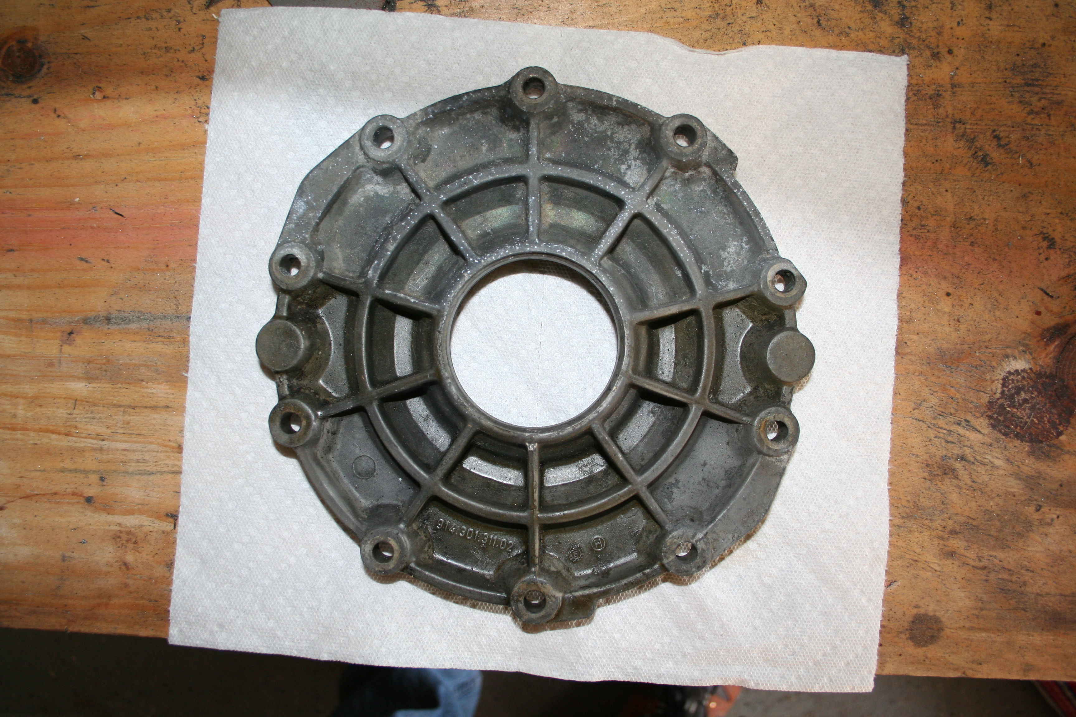
Here is the replacement sitting as well as the spot it will slot into. I still have some more work to do fabricating the replacement. Once it's done, I will weld it and the U channel reinforcement mentioned above in at the same time. Read more about the floorboard and seat repair work here Ok, time to look in on how the differential cover is doing. It actually sat in my garage for about two months after the cleaning and protection treatment in May of last year. So it it was actually outside hanging under my back porch for about six months. What I am seeing so far is...
Outside. Top section that was un-protected has corrosion. Both the Gibbs and CRC areas look pretty good with the CRC product looking better.
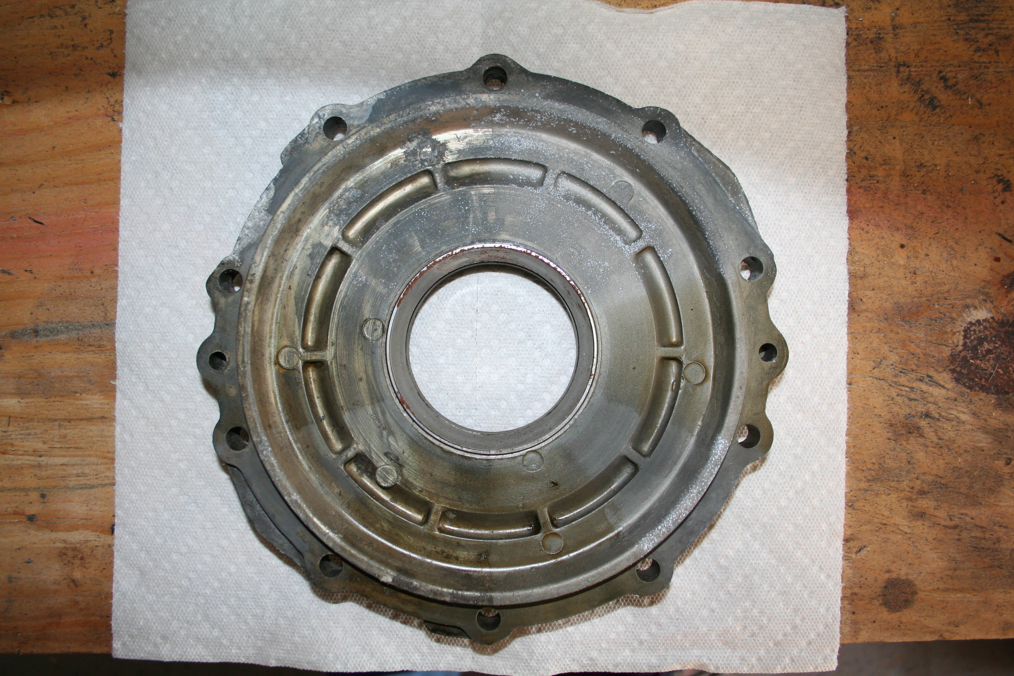
Inside. Like the outside the top section has corrosion. However the right hand side has more corrosion. That side was media blasted. If you look at the left side you can see that some of the original chromate conversion is still protecting the magnesium. My conclusion so far are...
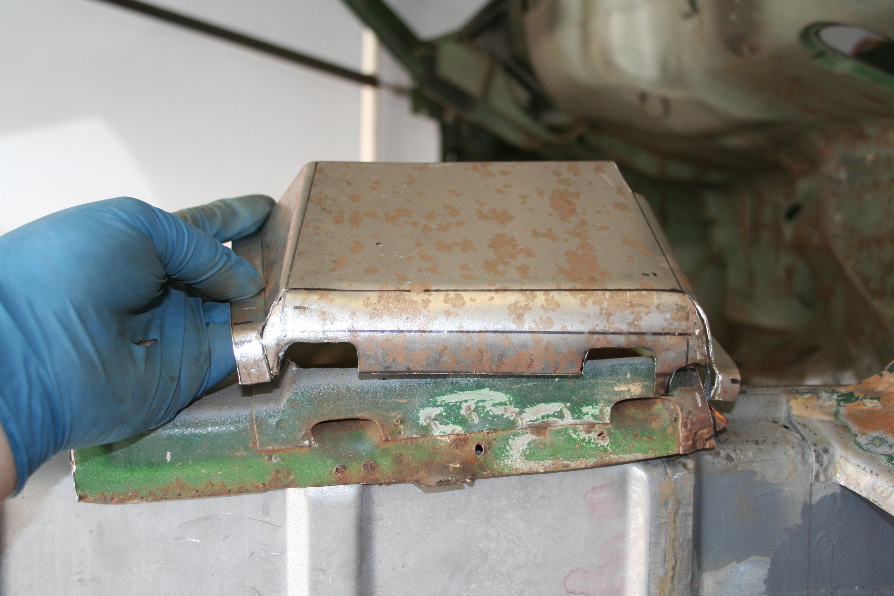
As I am not ready to start working on the transmissions, I expect the diff cover is going to go back out under my back porch until I am ready to start on the transmissions. Read more about transmission repair work here 1/11/2009Now I need to put the factory "U channel" reinforcement onto the bottom of the car. This reinforcement is right below the seat hinges. The floor has a "U channel" pointing up that is part of the floor and the weld on reinforcement points down. It makes a small box section. I have always wondered if this is a place that rust starts. I drilled out the spot welds on the old floor section and removed the factory U channel and other than some surface rust it doesn't look too bad.
It's hard to tell in this photo, but this is the U channel laying on the old floor section after the spot welds have been drilled out and it was popped loose.
After some time in the blast cabinet, some metal ready and some POR-15, it's all ready to be welded back together. Before I weld, I will grind off small spots in the POR-15 as you can't weld through it. Read more about the floorboard and seat repair work here 1/4/2009It's hard to believe that it's been nearly a year since I created the replacement floor section, but it is now welded in. I figured I deserve an "action" shot of me working on the car. If I knew I was planning on doing this, I might have taken a show beforehand. However this is my "roll out of bed and start grinding welds in a cold garage" look.
Read more about the floorboard and seat repair work here |
|