![]()
![]()
|
|
|
|
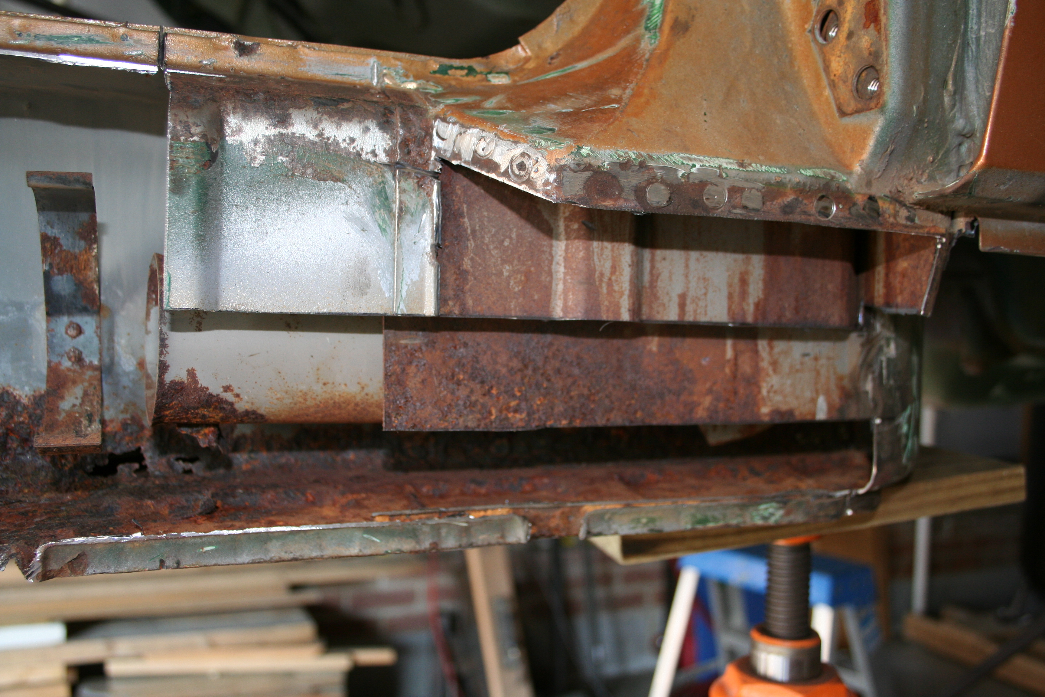
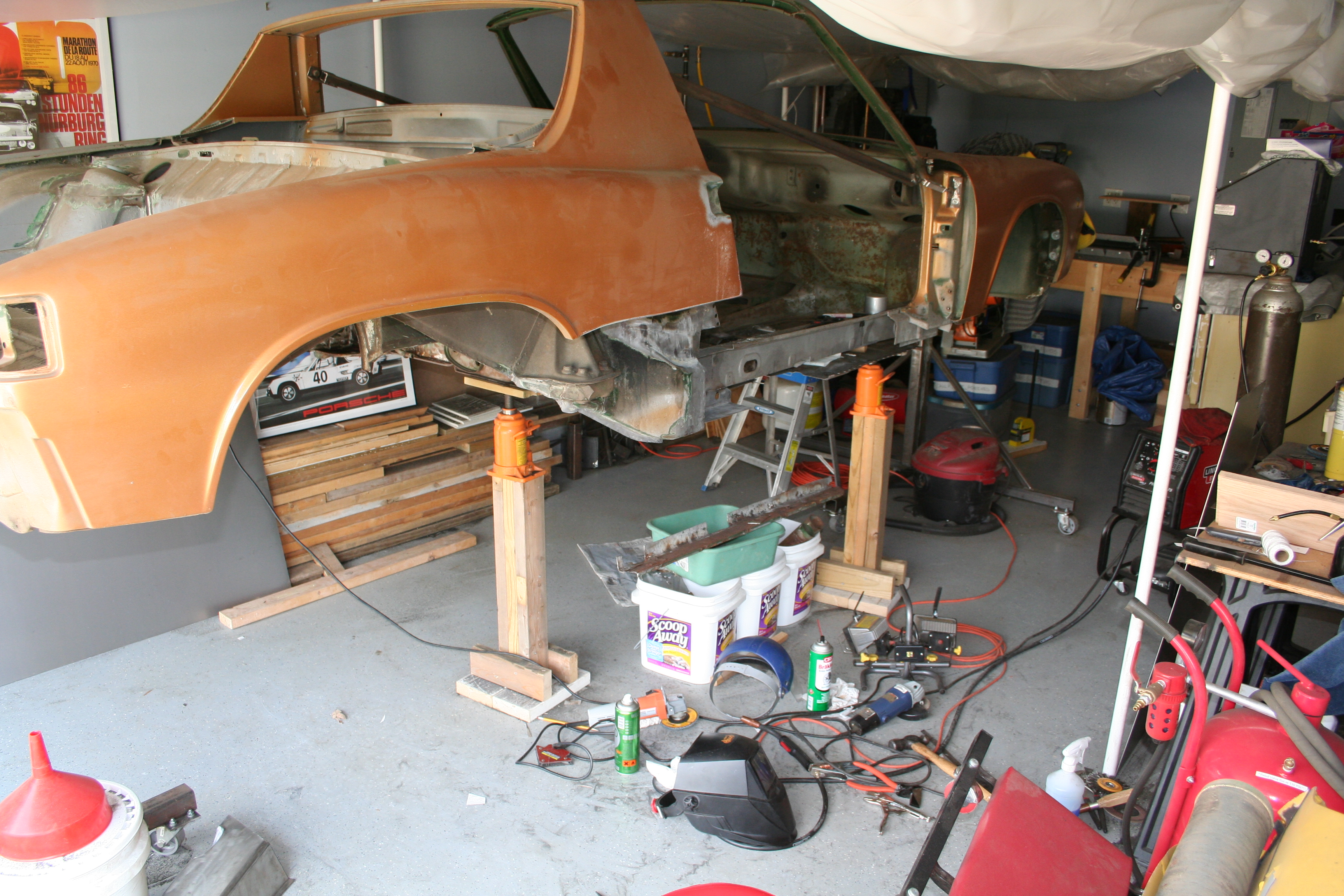
1972 Porsche 914Repair and Restoration - Part 4 - Passenger Side Longitudinal7/8/2007To repair the outside of the passenger side longitudinal, the passenger jack point and part of the hell hole, I have decided to cut away part of the bottom of the rear fender. Otherwise access to the this area would be very hard.
Cut along the marked line with a reciprocating saw.
Use spot weld bits to remove sill and rear fender section.
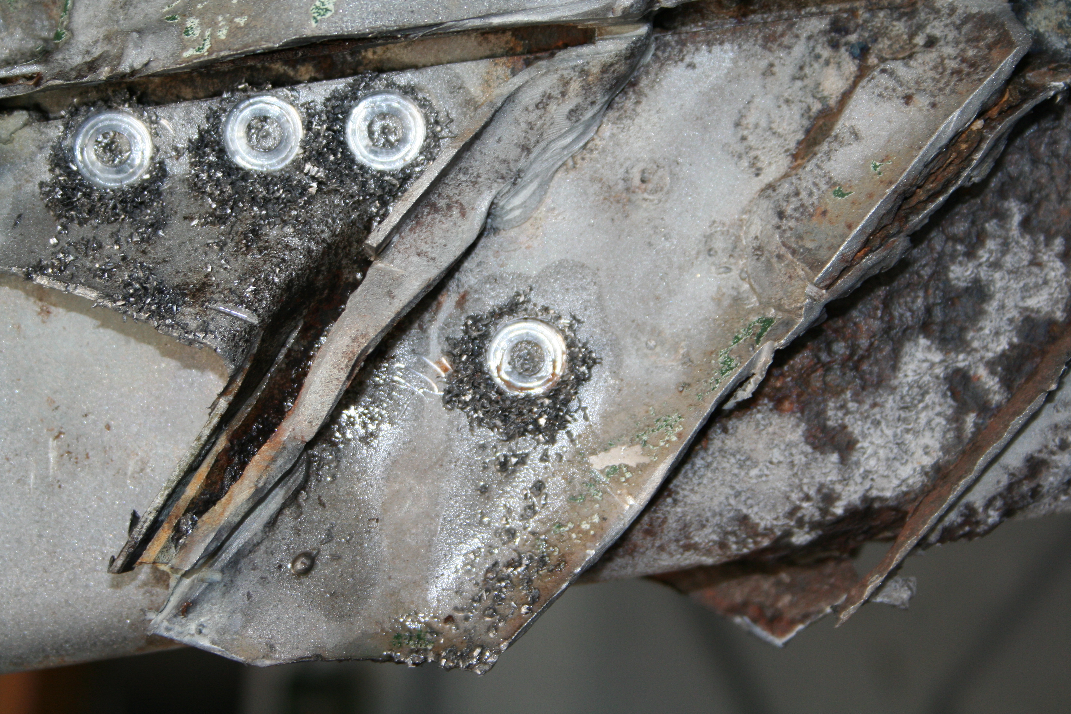
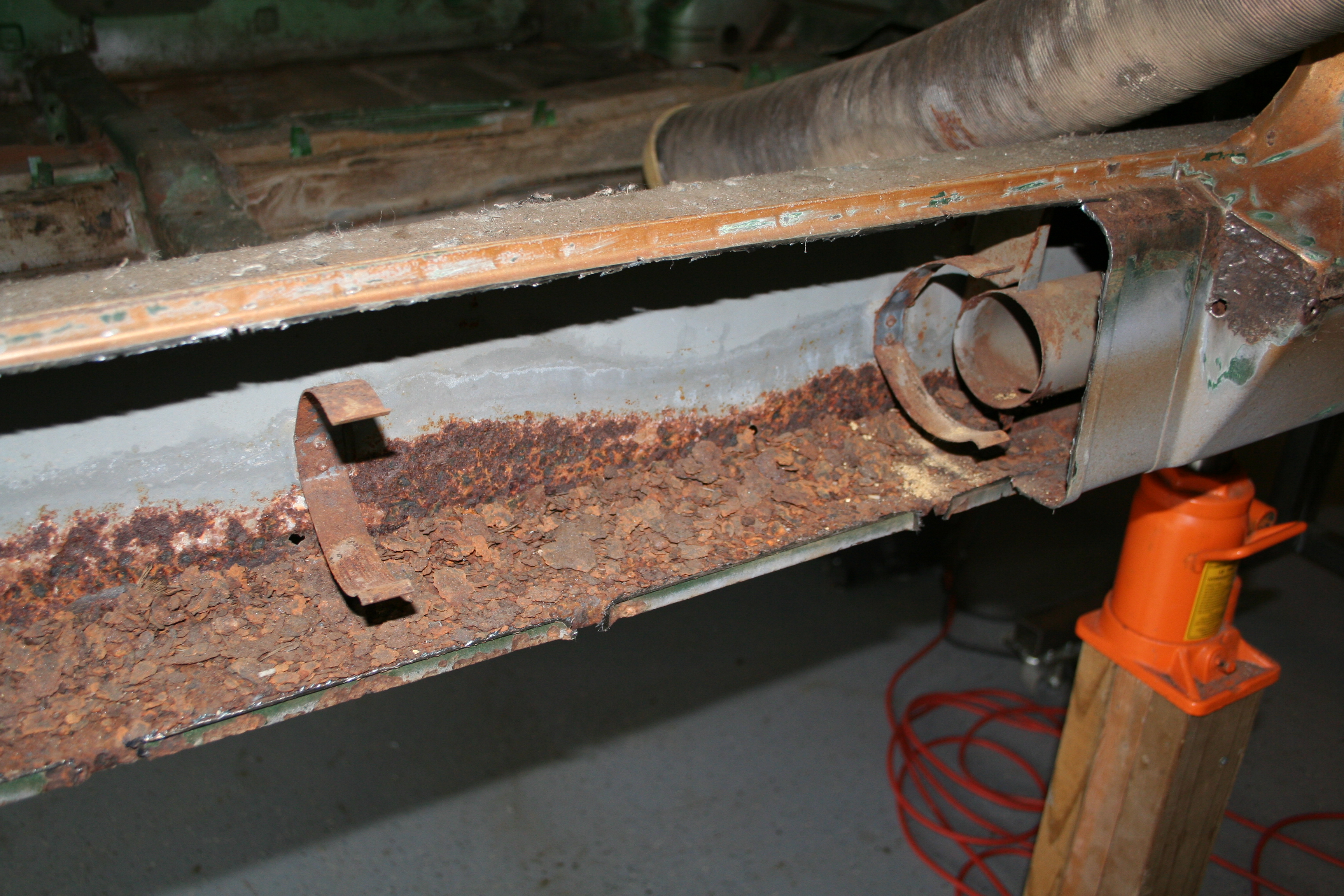
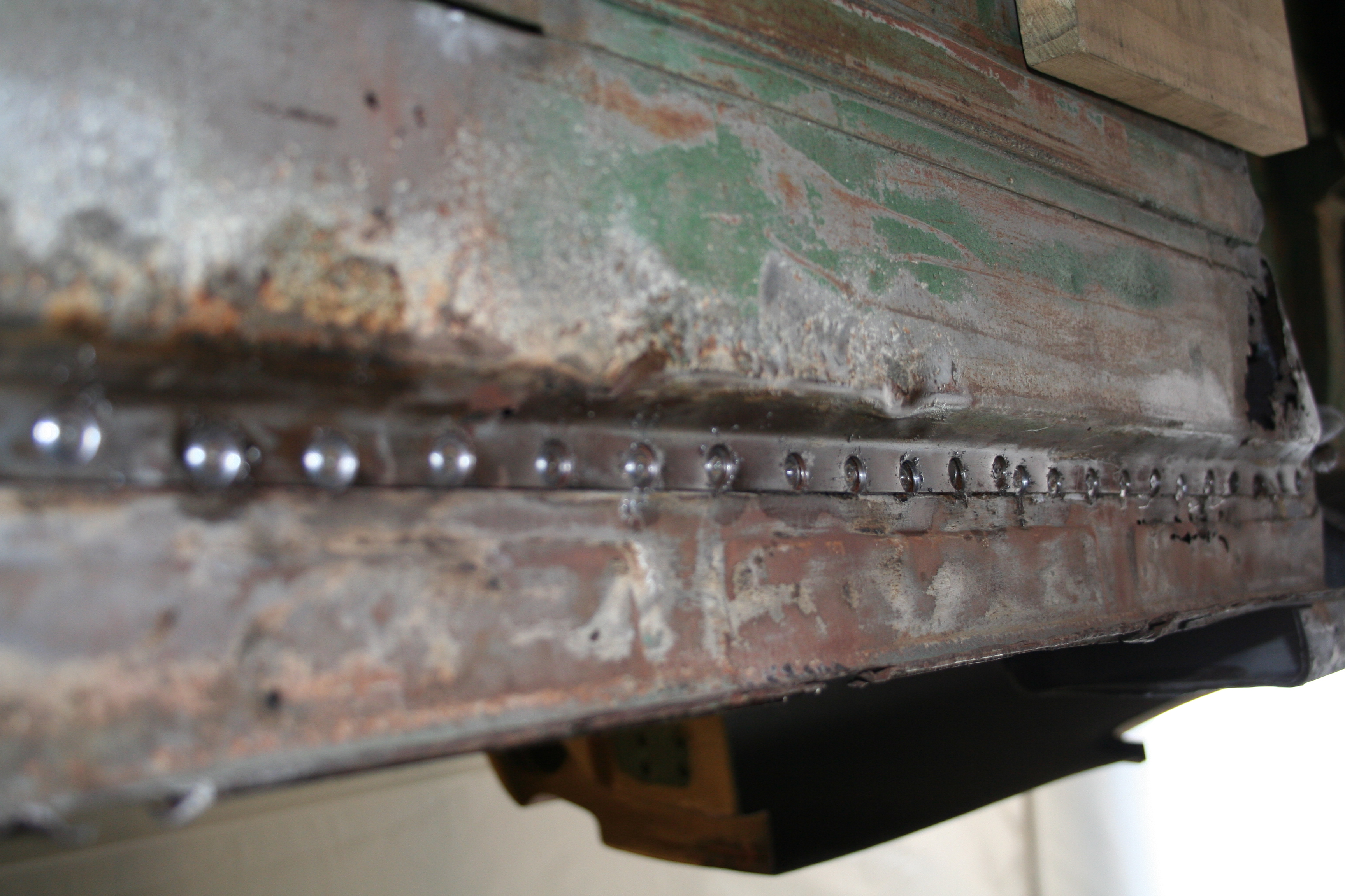
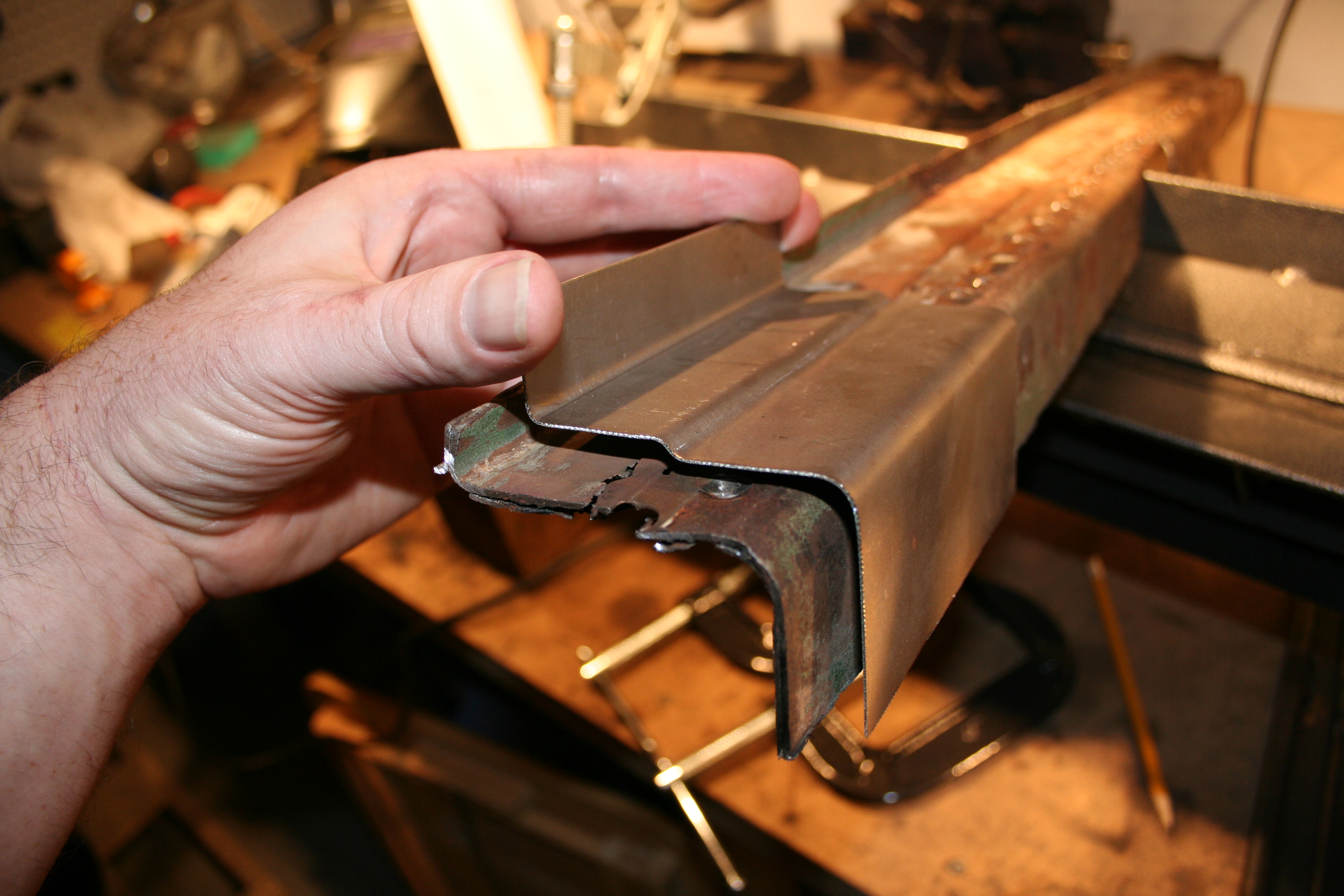
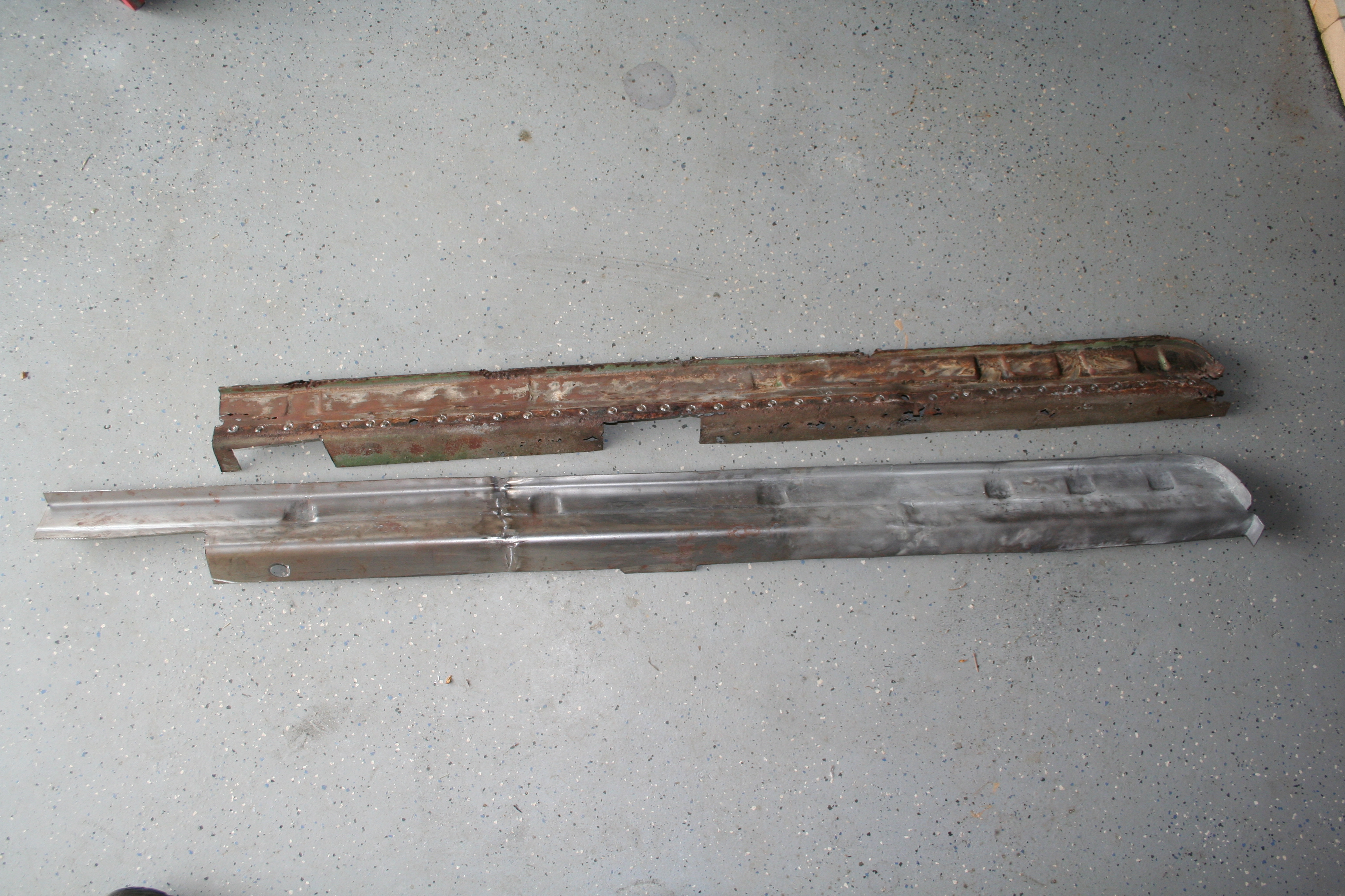
See the pinholes in the outer longitudinal? This section needs to be replaced as I am sure it is much worse on the inside. 10/13/2007Ongoing work on trying to remove various stuff from the longitudinal. This consists mostly of things like the remnants of the donut plate, four cylinder engine mount and inner suspension console.
Results of using the Blair Rotabroach spot-weld bit.
Detail of drilling out spot welds. This area is a total pain as you have spot welds covered by other plates that have been both spot welded and stick welded into place. 10/25/2007Been working on getting ready to remove the outer longitudinal. Been thinking about how to do the section near the front. It has some rust that needs to be repaired and the replacement longitudinal (if I use all of it) would go underneath of this box section below the door hinges.
10/26/2007Today is the day to start cutting! First some photos of what I built and installed yesterday.
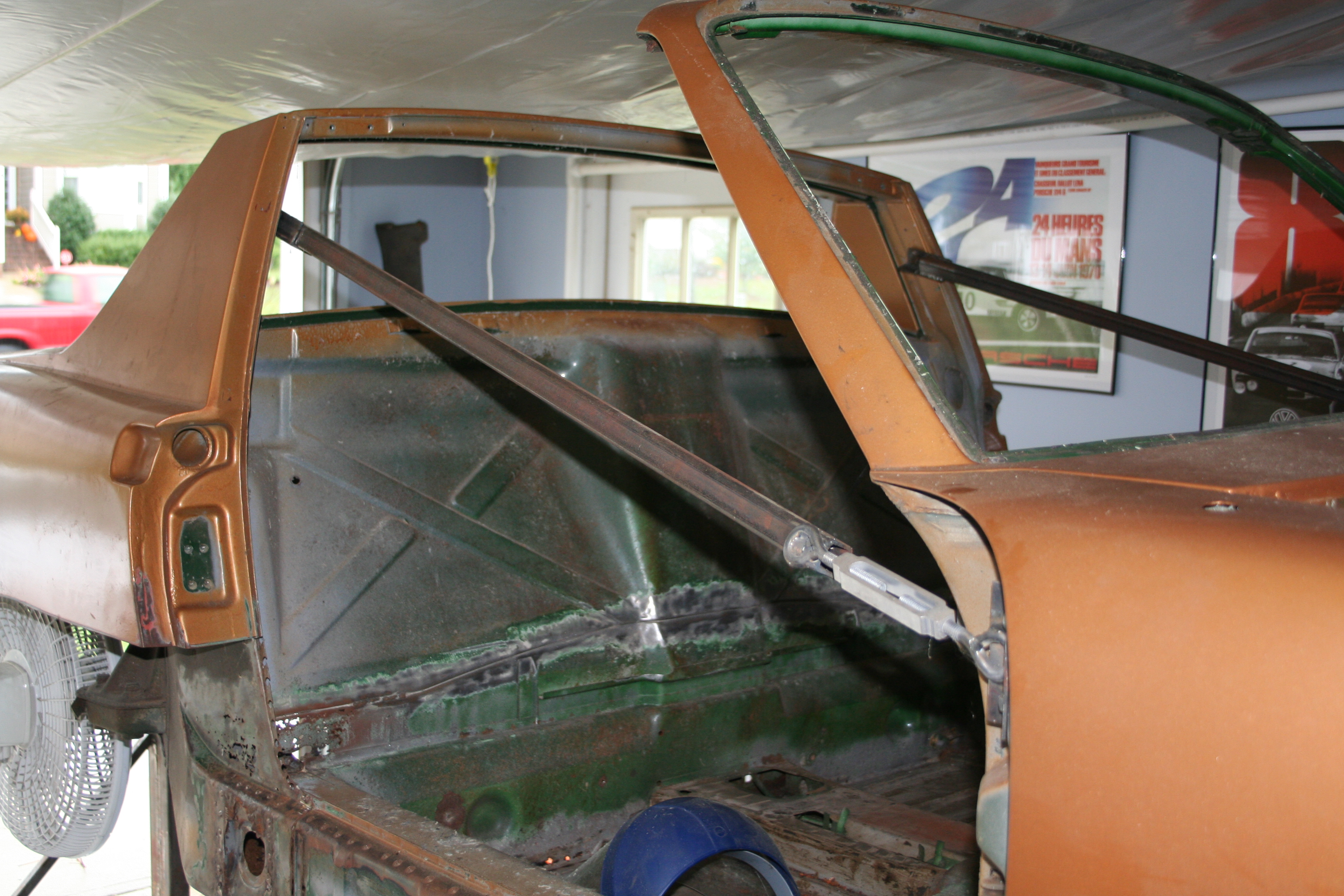
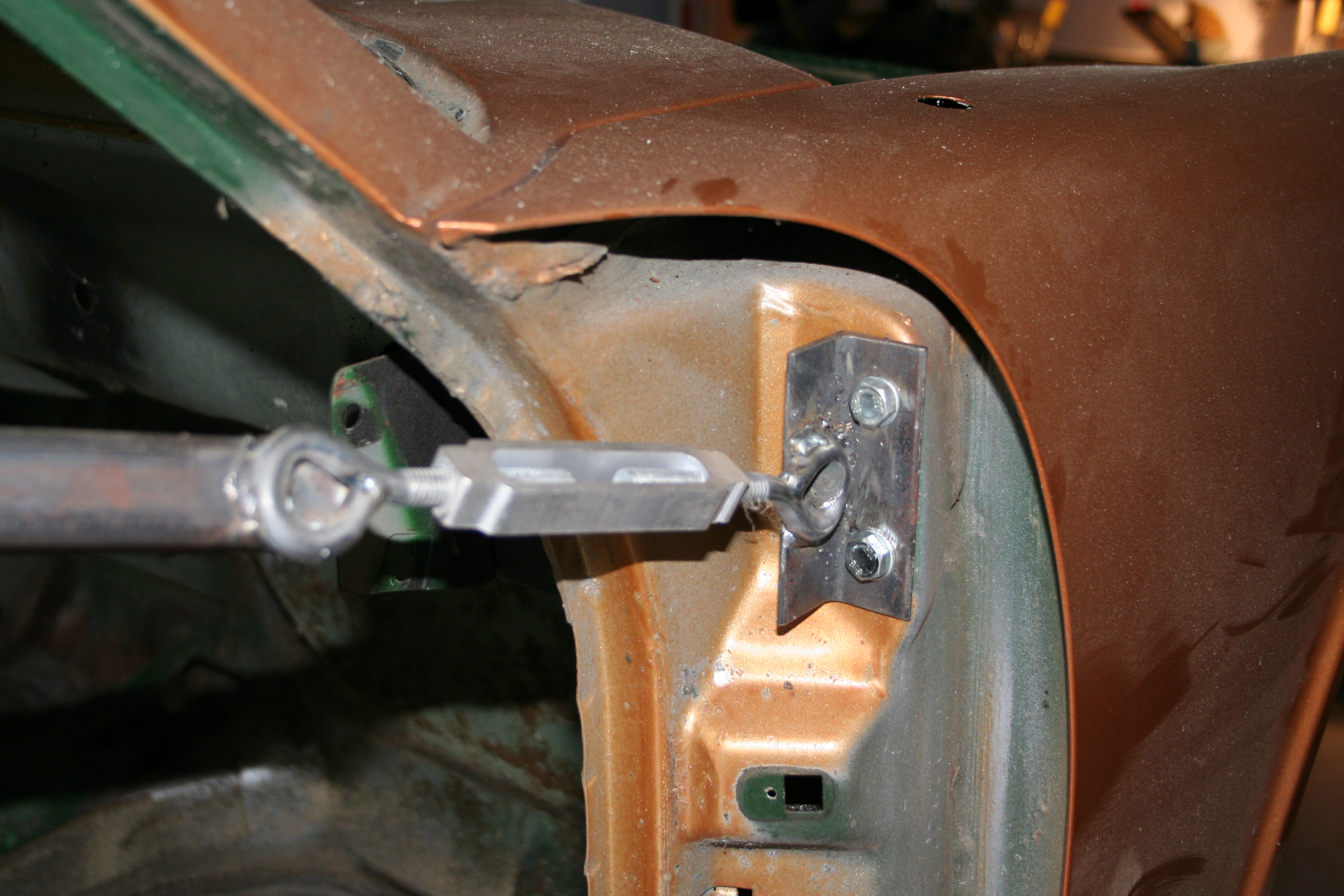
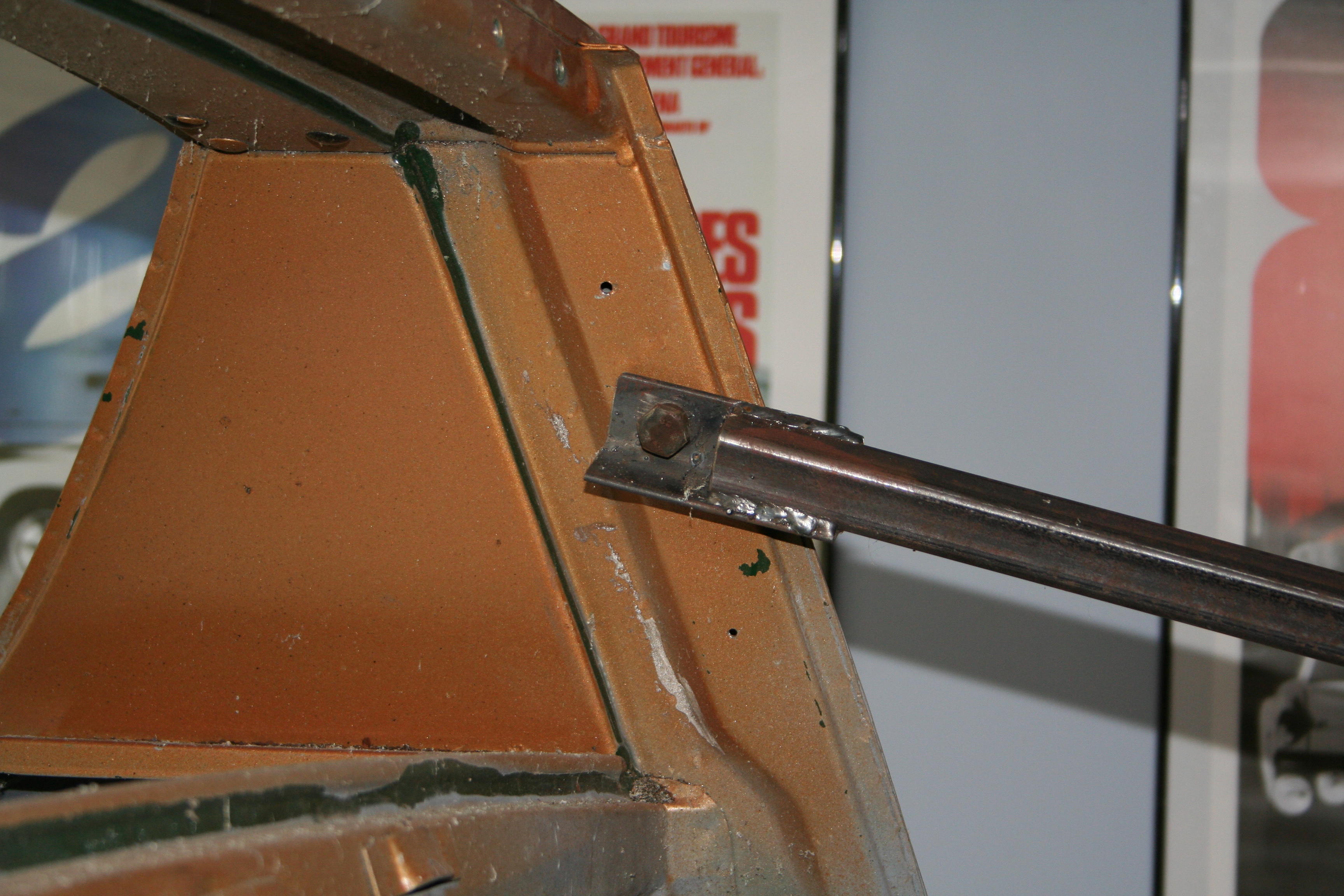
While I will have braces in the doors (see below), I don't want them to carry 100% of the load while the car is suspended on the rotisserie. So I am going to lock the rotisserie with the car being exactly level (left to right) and then also put bracing under the car at the front and rear of the longitudinal on the side that I am working on. I built some wood braces (sort of like jack stands), but I used three 2x4s and there is space at the top for a hydraulic bottle jack. I wanted to be able to adjust the pressure on these as I worked. I am a little concerned about these bleeding down, but I have used these jacks before and have not had problems with them bleeding down. Also the car at this point is pretty light.
One last item that I have not installed on the car was the door braces. These mount using the shoulder harness mount and the upper door hinge mount. They each have a turnbuckle so make the bar shorter or longer. These are to help take the load off the longitudinal while they are cut apart and to maintain the factory spec distance between the the Targa bar and the windshield. Both sides currently are at factory spec prior to surgery (a good thing). I had built these braces months ago, but I was having a hard time getting the top ends to bolt to the shoulder harness mounting point. I just couldn't find a bolt that worked!. The existing bolts was packed away and I knew the bolt was roughly a 10mm bolt. I bought a couple 10mm with different thread pitches and none worked. And 12mm was too big. Could this be an 11mm bolt? That seemed an odd size. I ended up digging out the factory bolts and sure enough as far as I can tell they are 11 x 1.25 bolts.
Moment of truth. It is about what I expected.
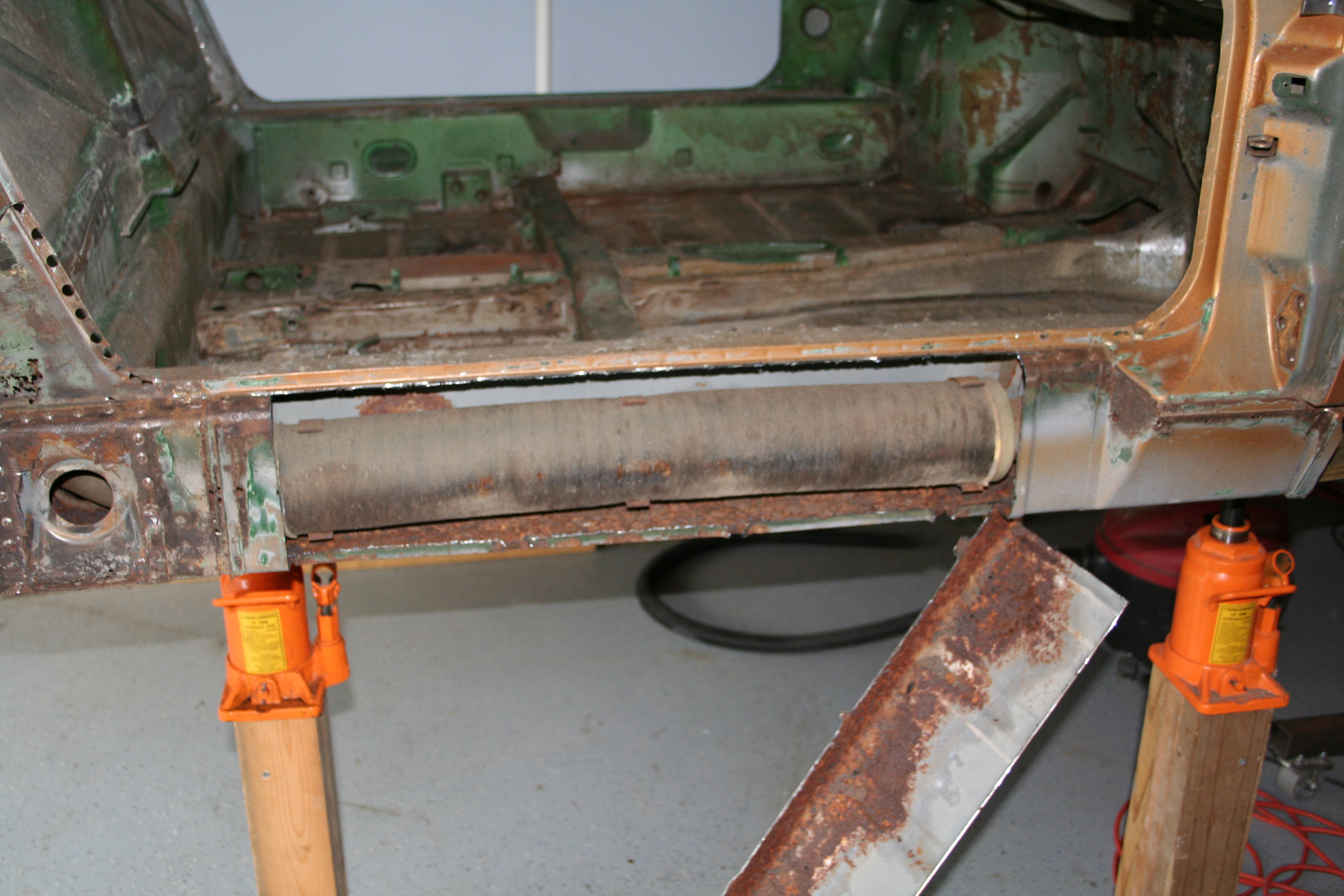
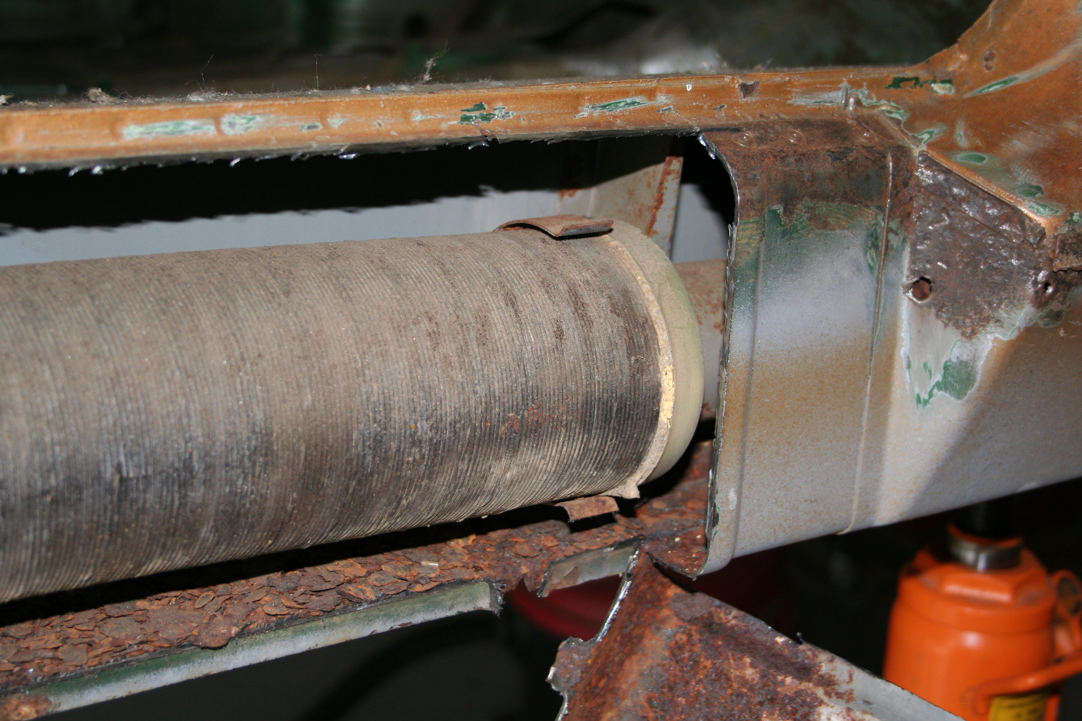
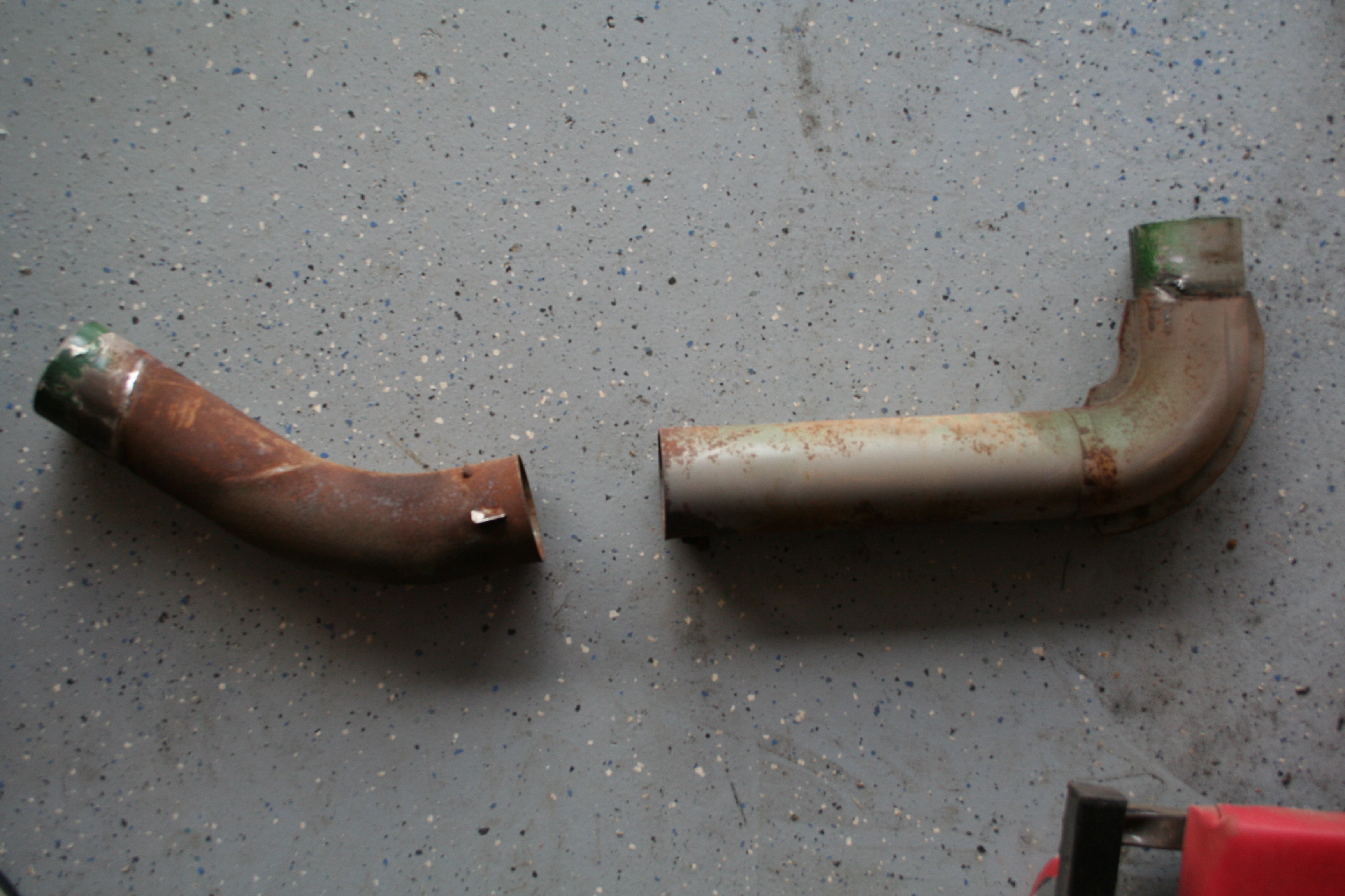
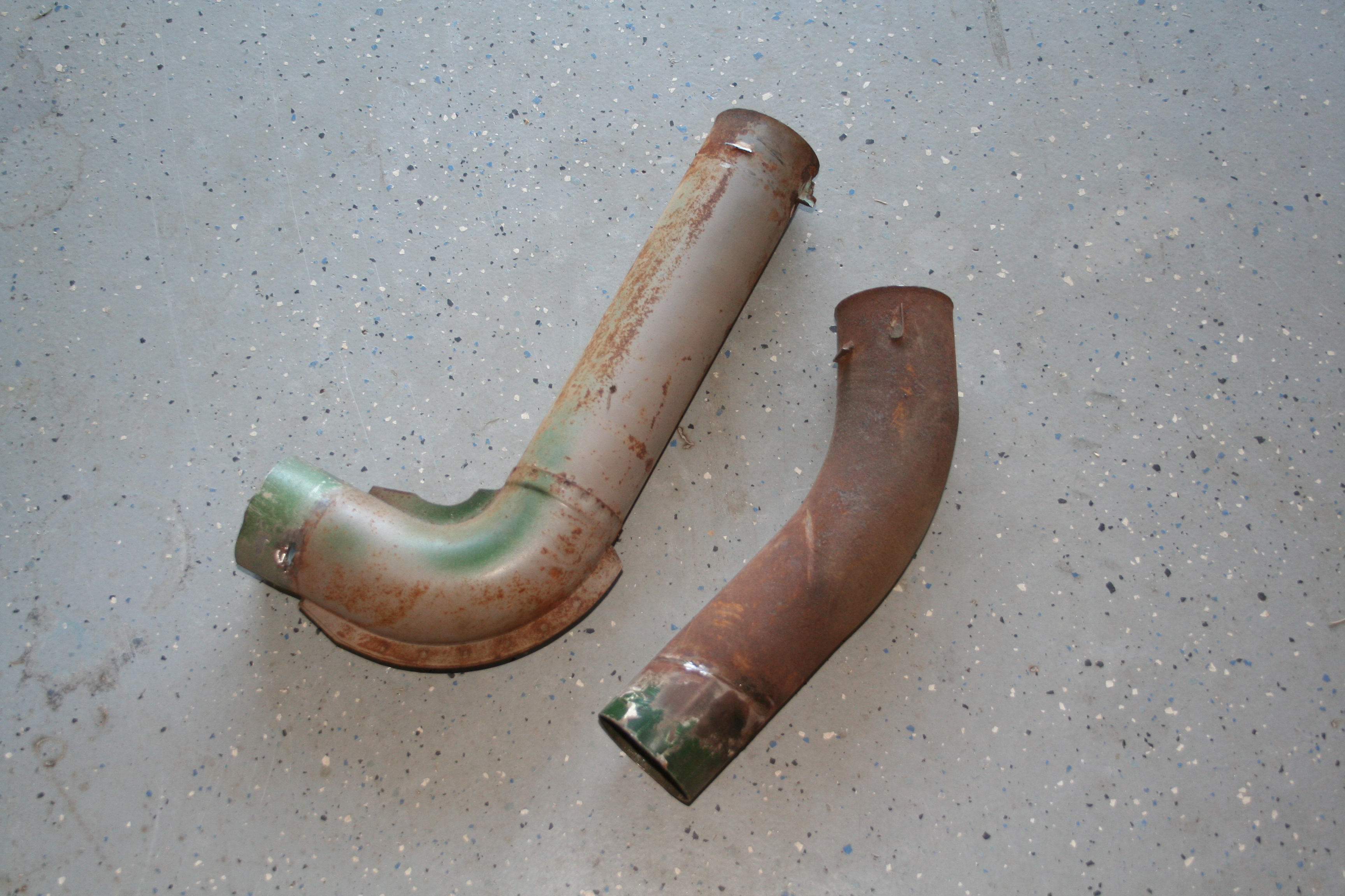
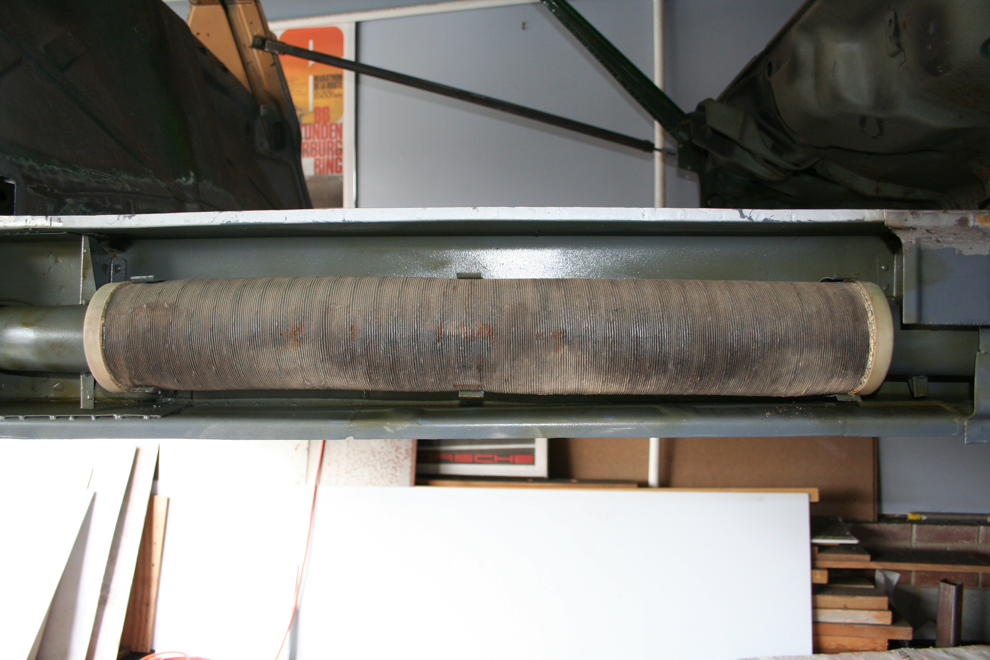
I had always wondered why Porsche didn't just put a solid tube through the longitudinal. But the heater pipe is actually double walled. I am guessing it has insulation in-between the walls. So the reason for this type of heater tube must have been an attempt to keep the "hot air hot". One significant roadblock to having your car dipped in a caustic bath to remove rust is that you first need to remove this heater tube (otherwise it will deteriorate and you will not be able to have heat in the car as well as the resulting debris left over). The removal and restoration of this is not a simple task.
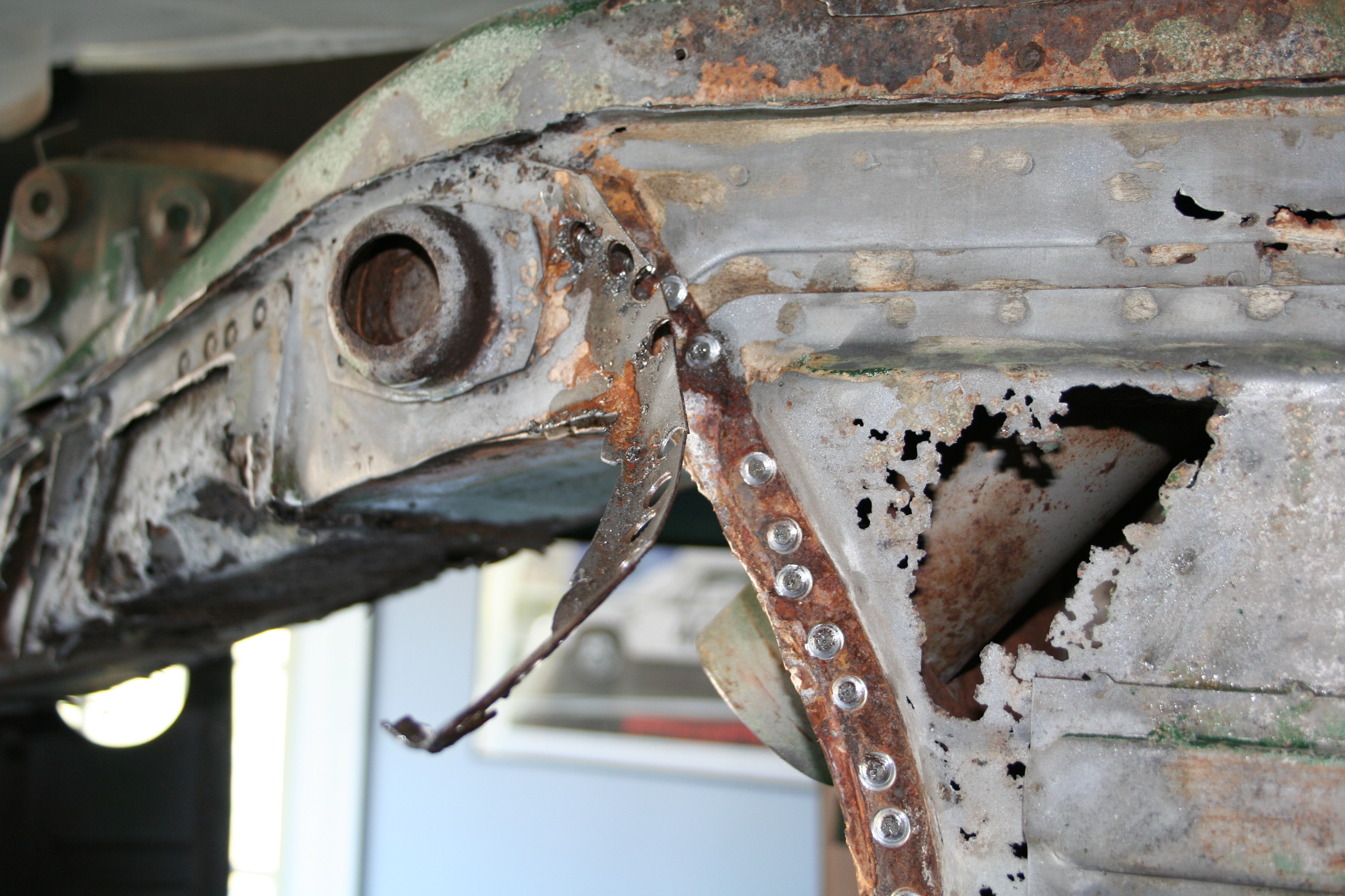
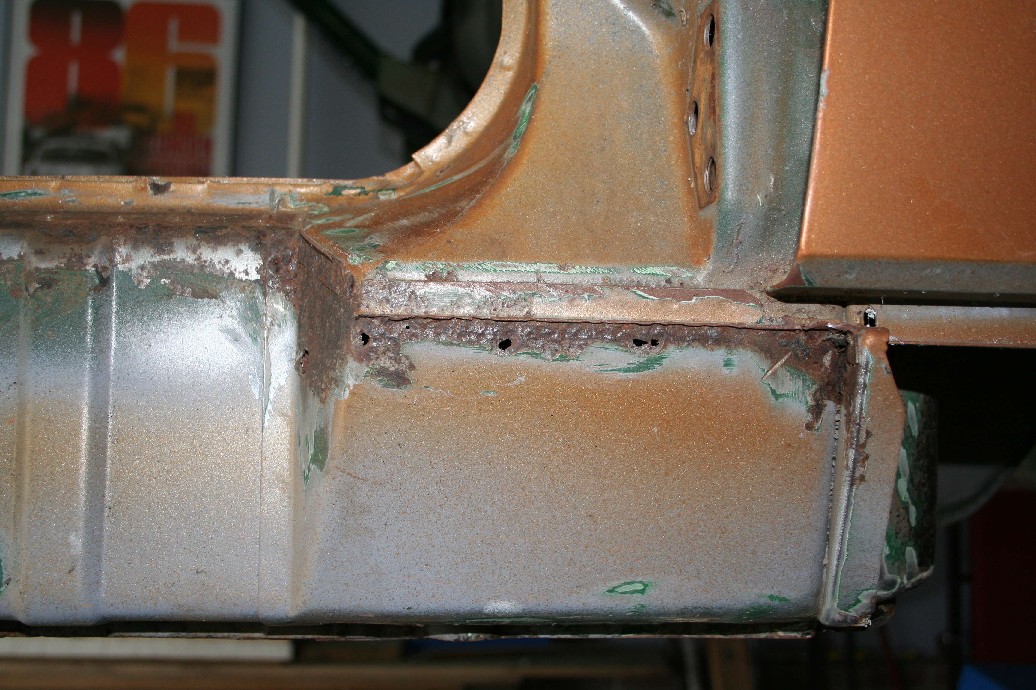
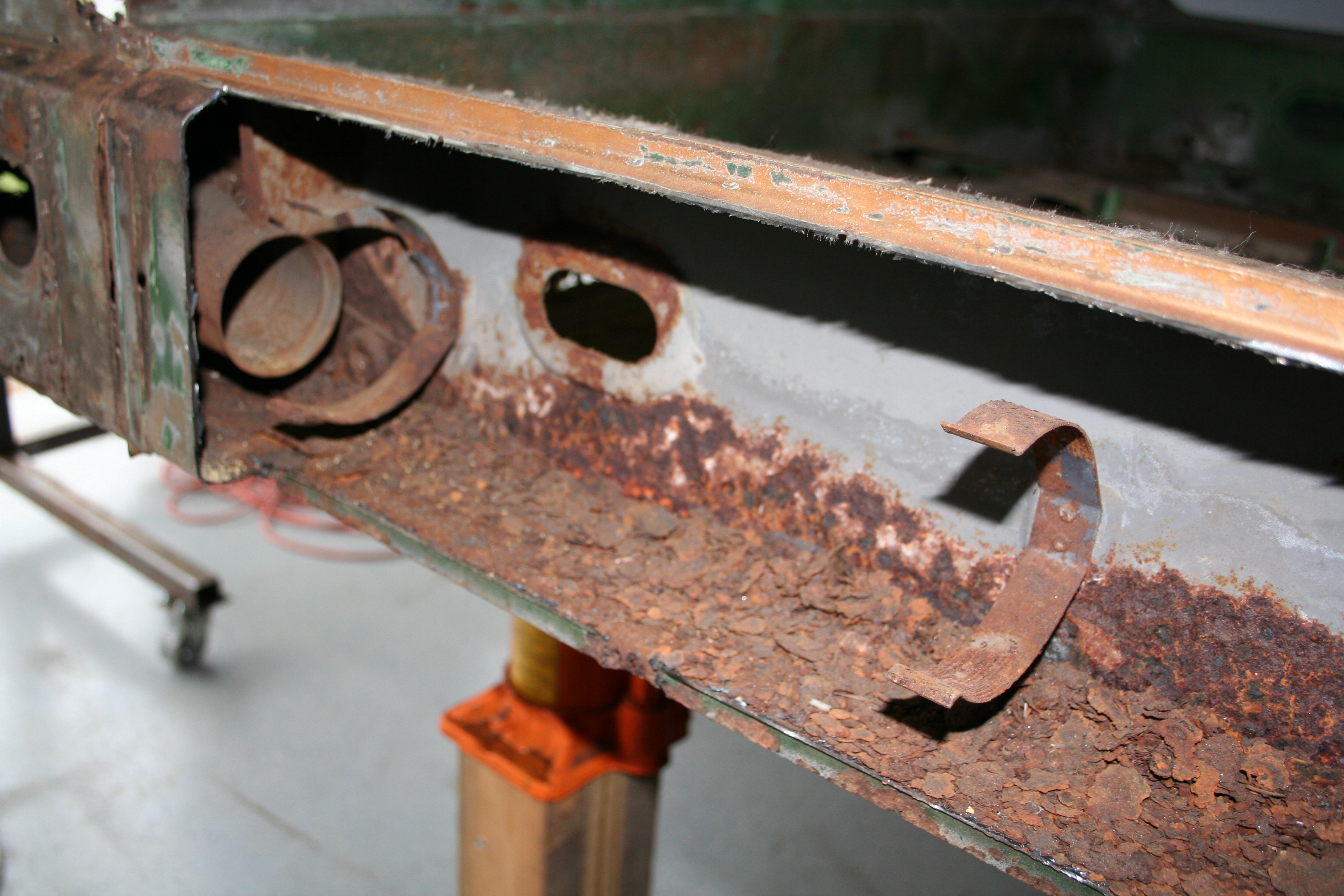
Lots of rust laying in there. I would say a good 1/2 is from farther up the box section from the Hell hole area.
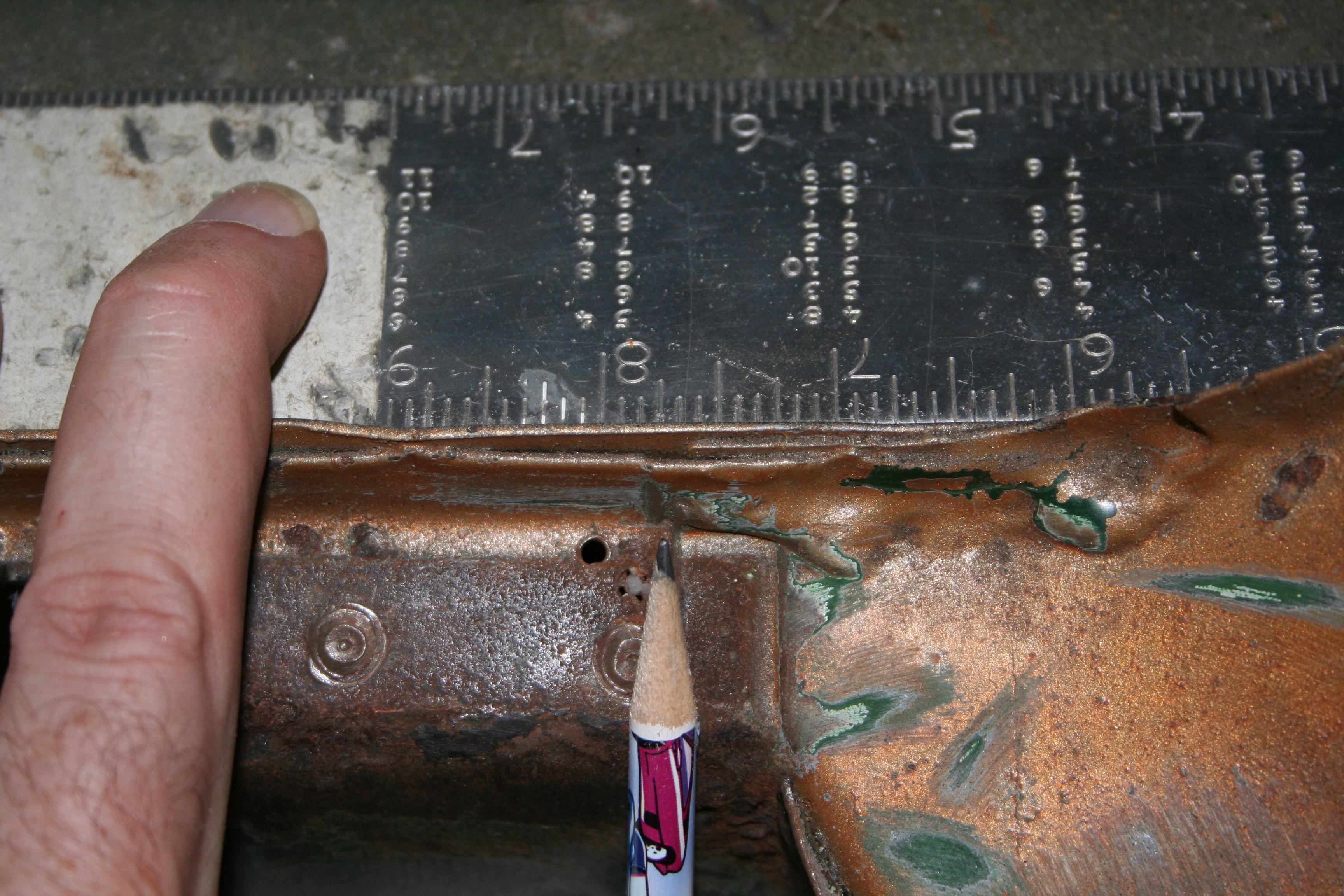
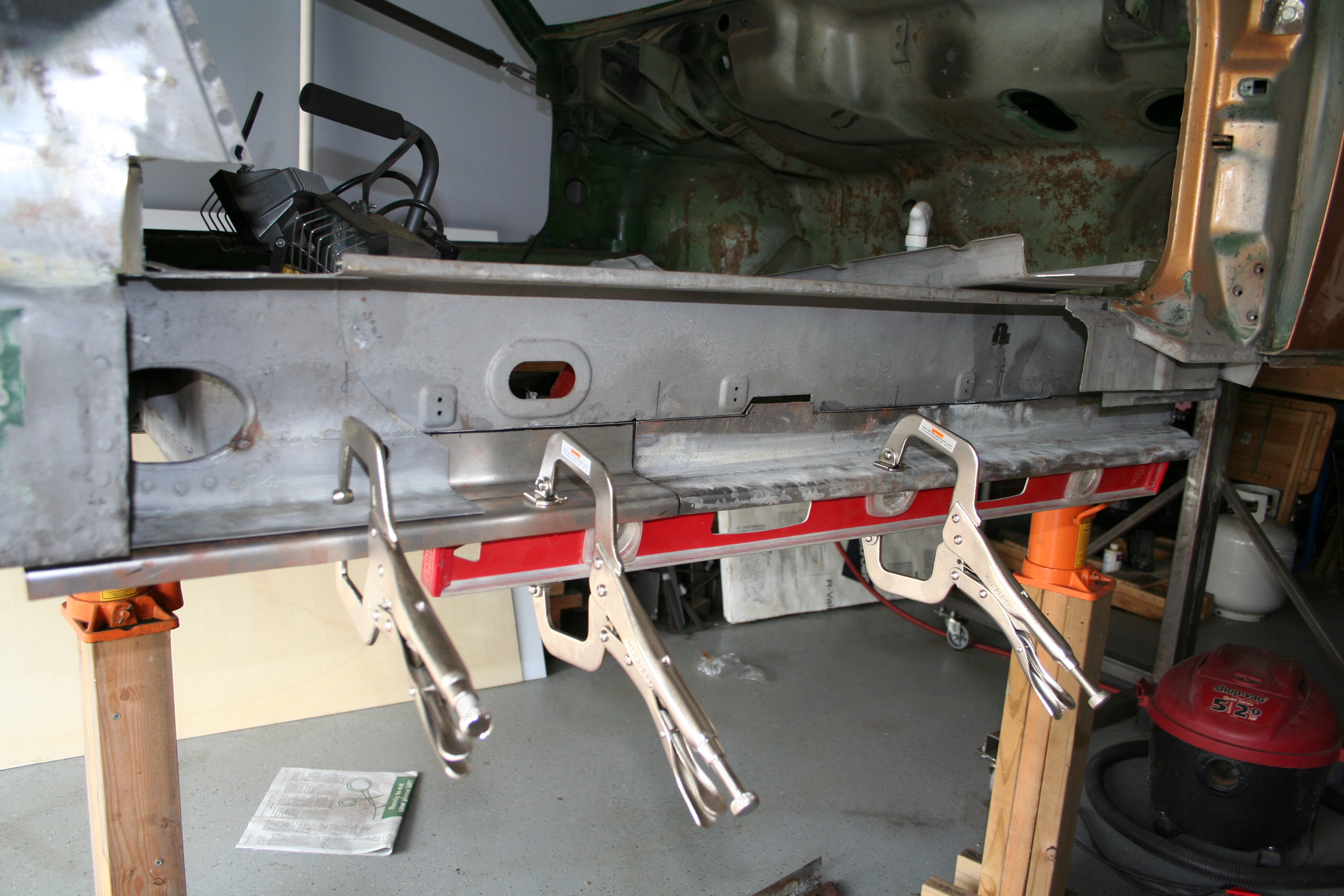
I wanted to document exactly where the seam was for the outer longitudinal. Measure from the firewall, it looks to be 3 7/8 inch.
Another measurement. But now that I think about it, I may not need this. But if I do, it was taken from the edge of the heater pipe.
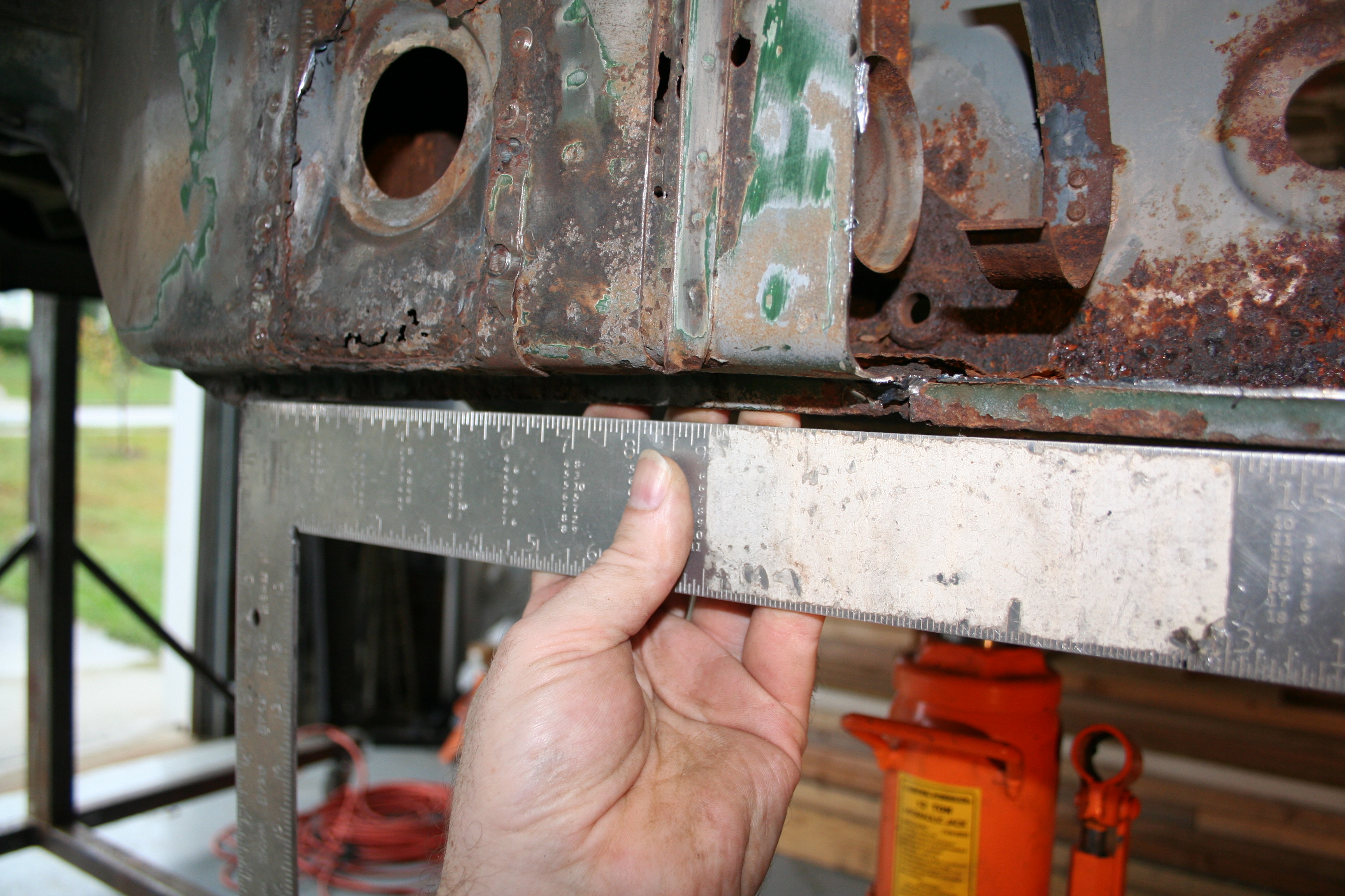
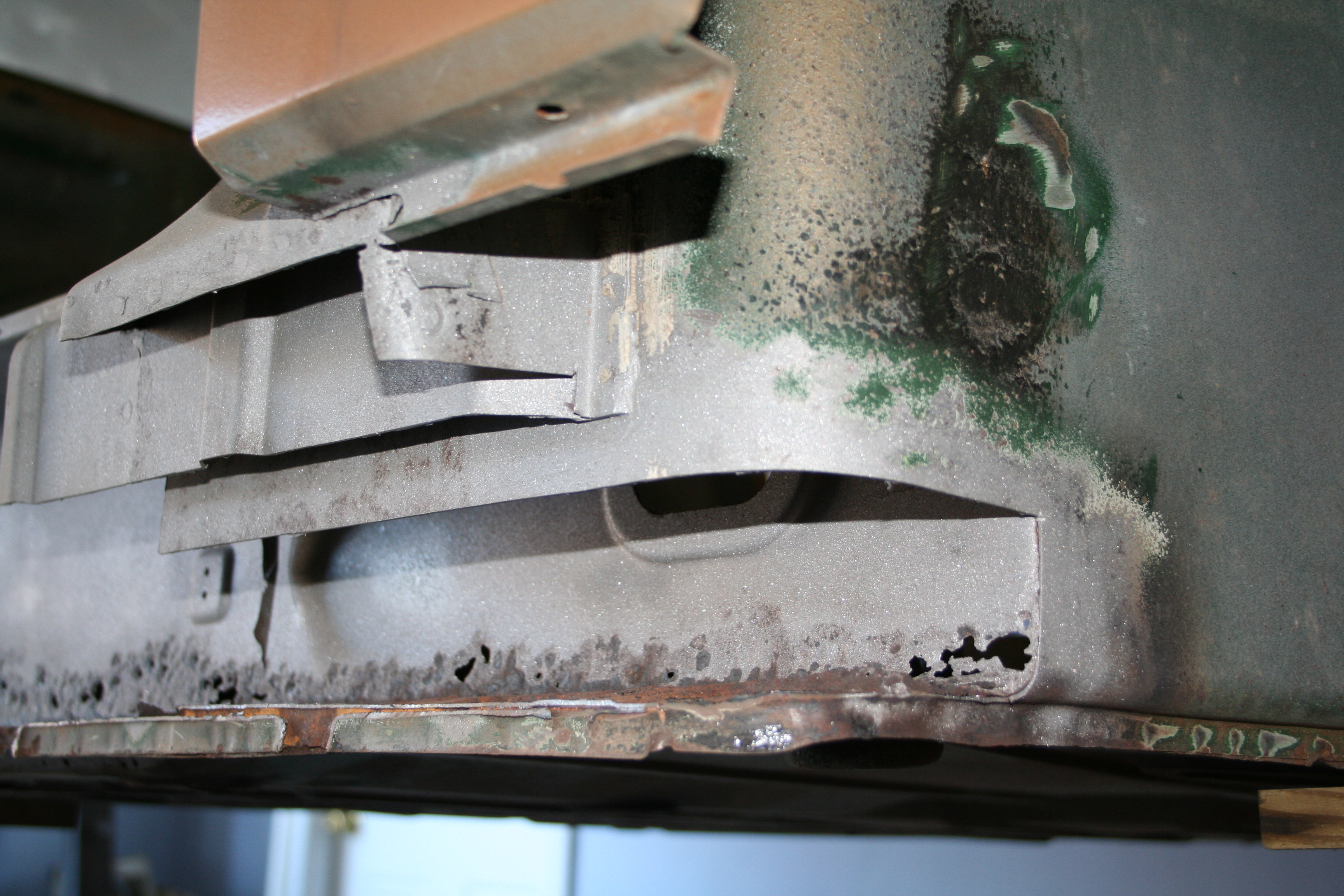
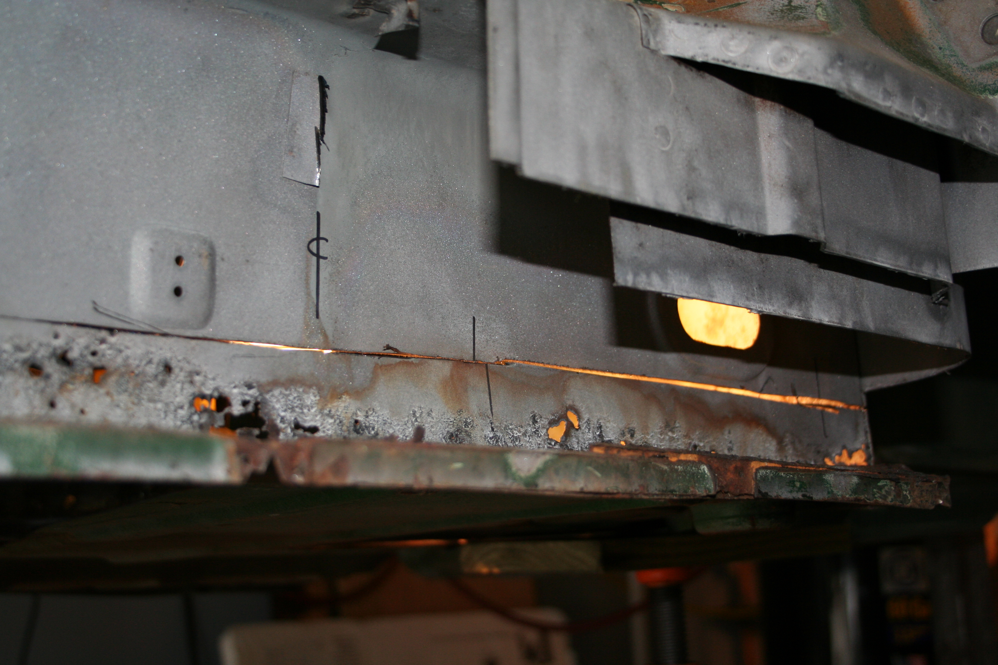
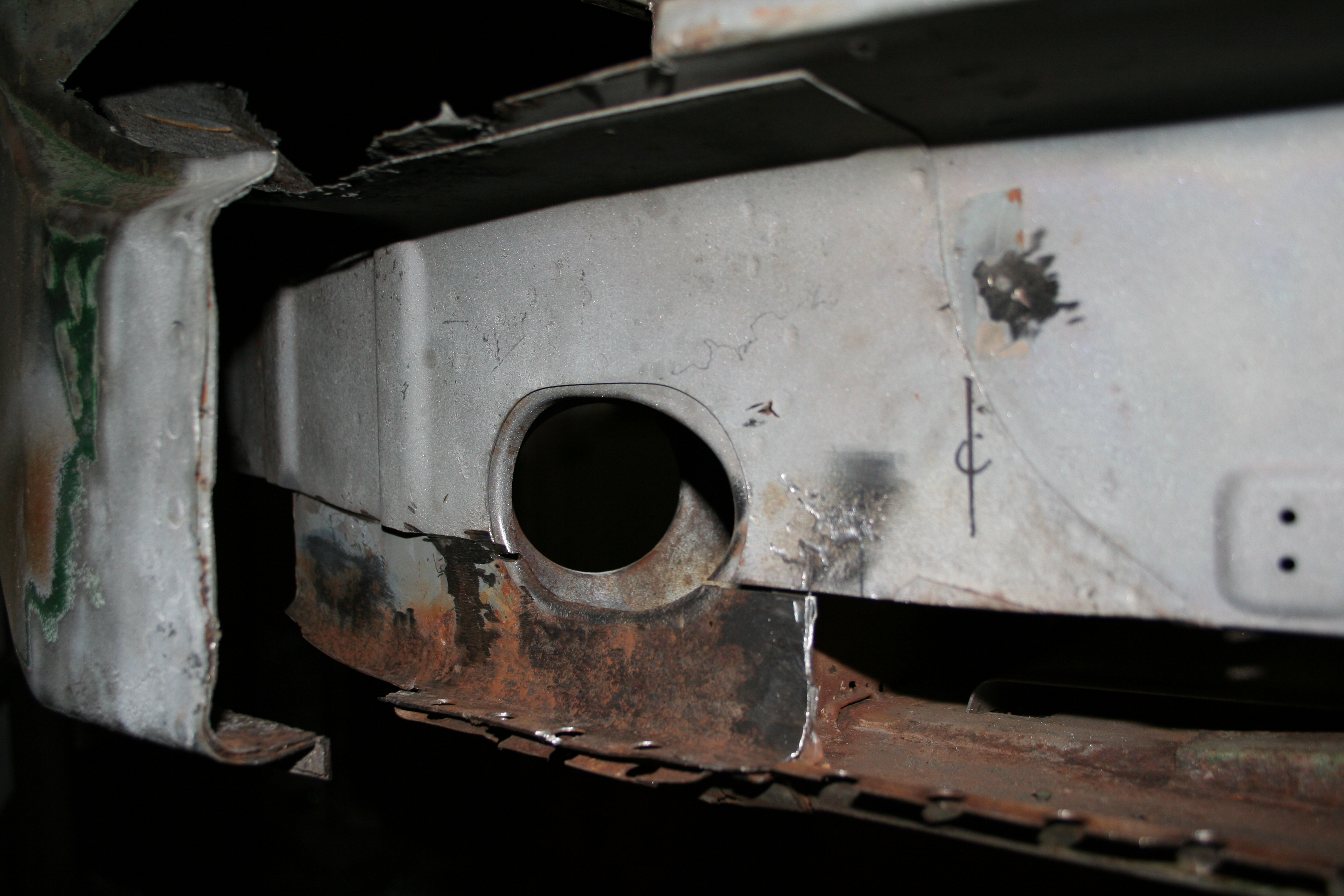
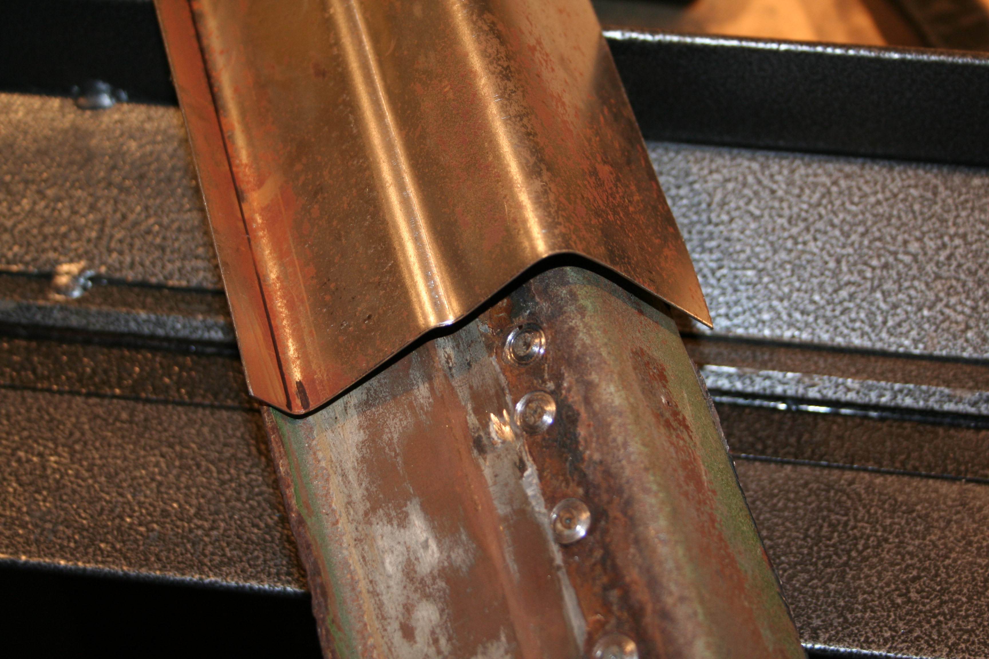
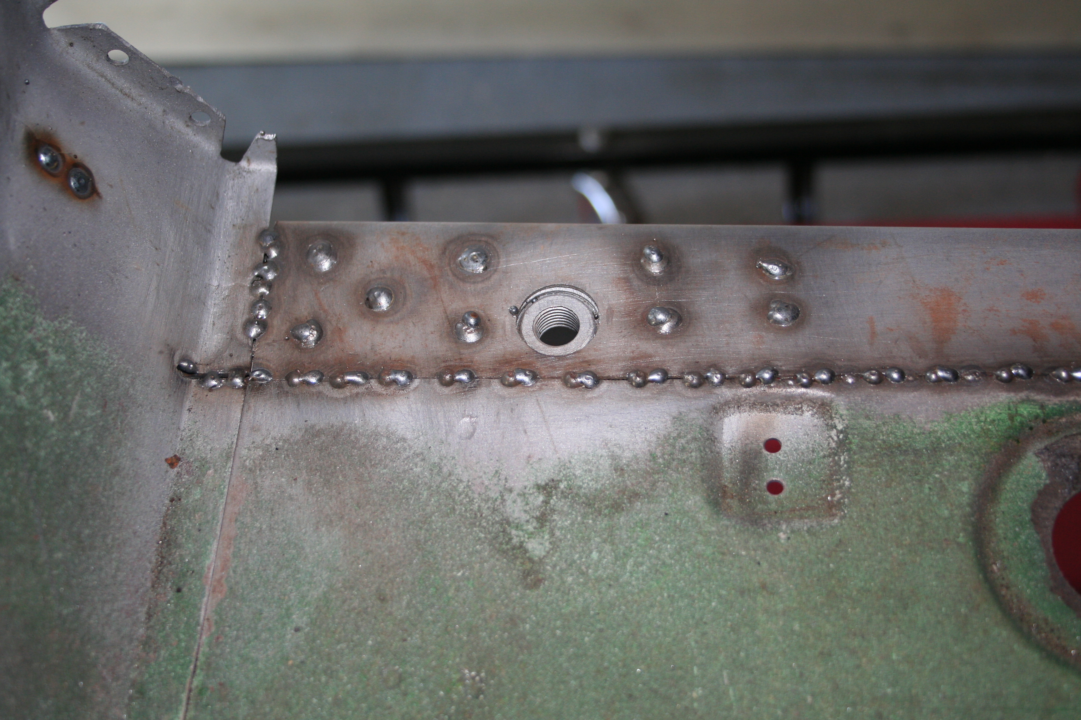
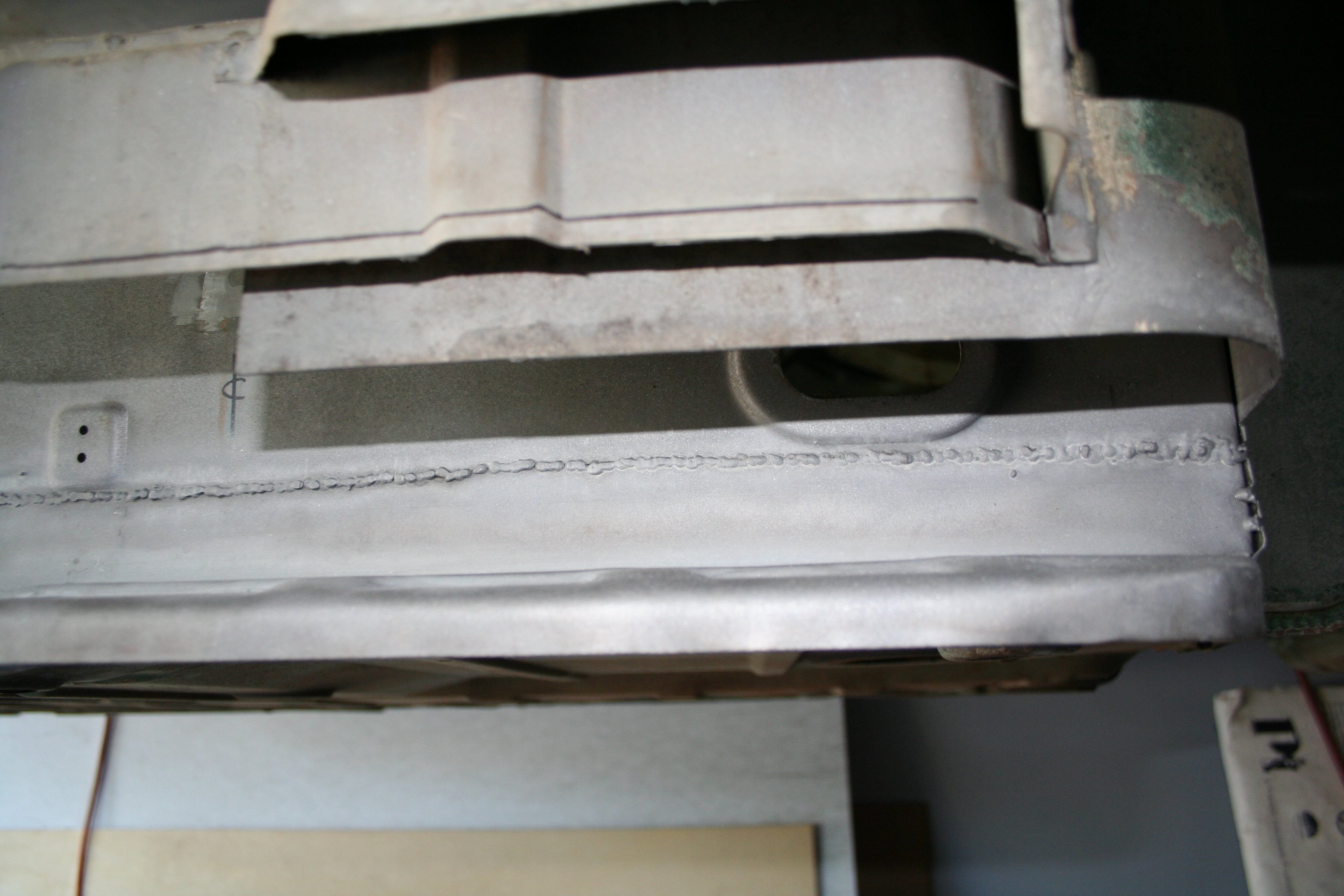
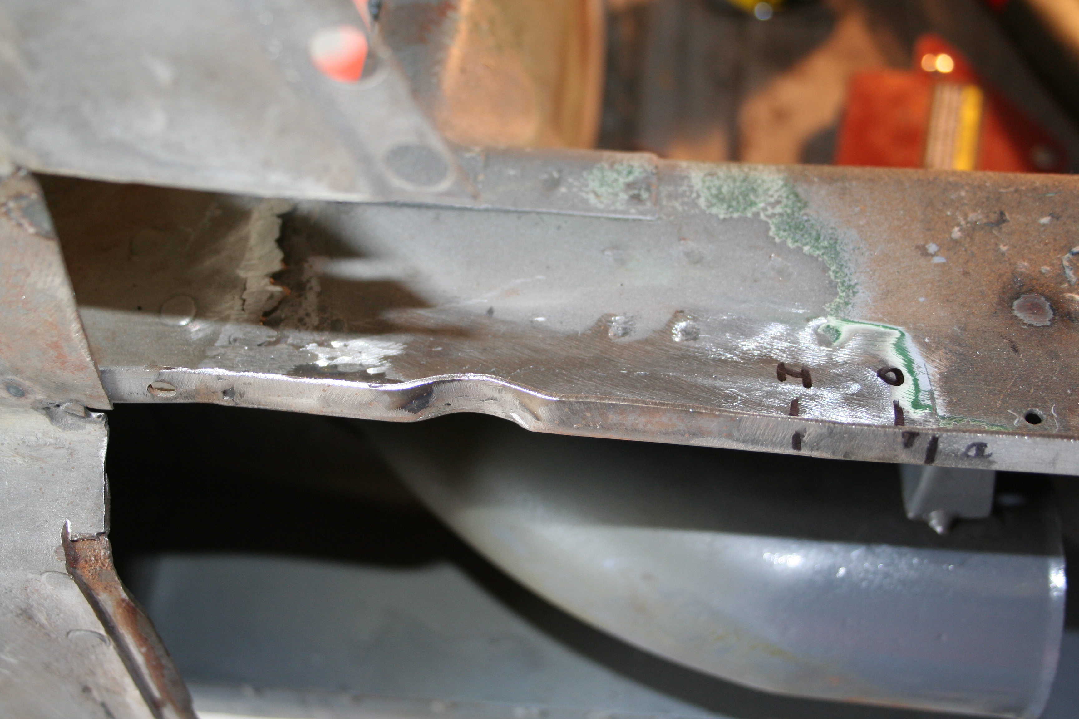
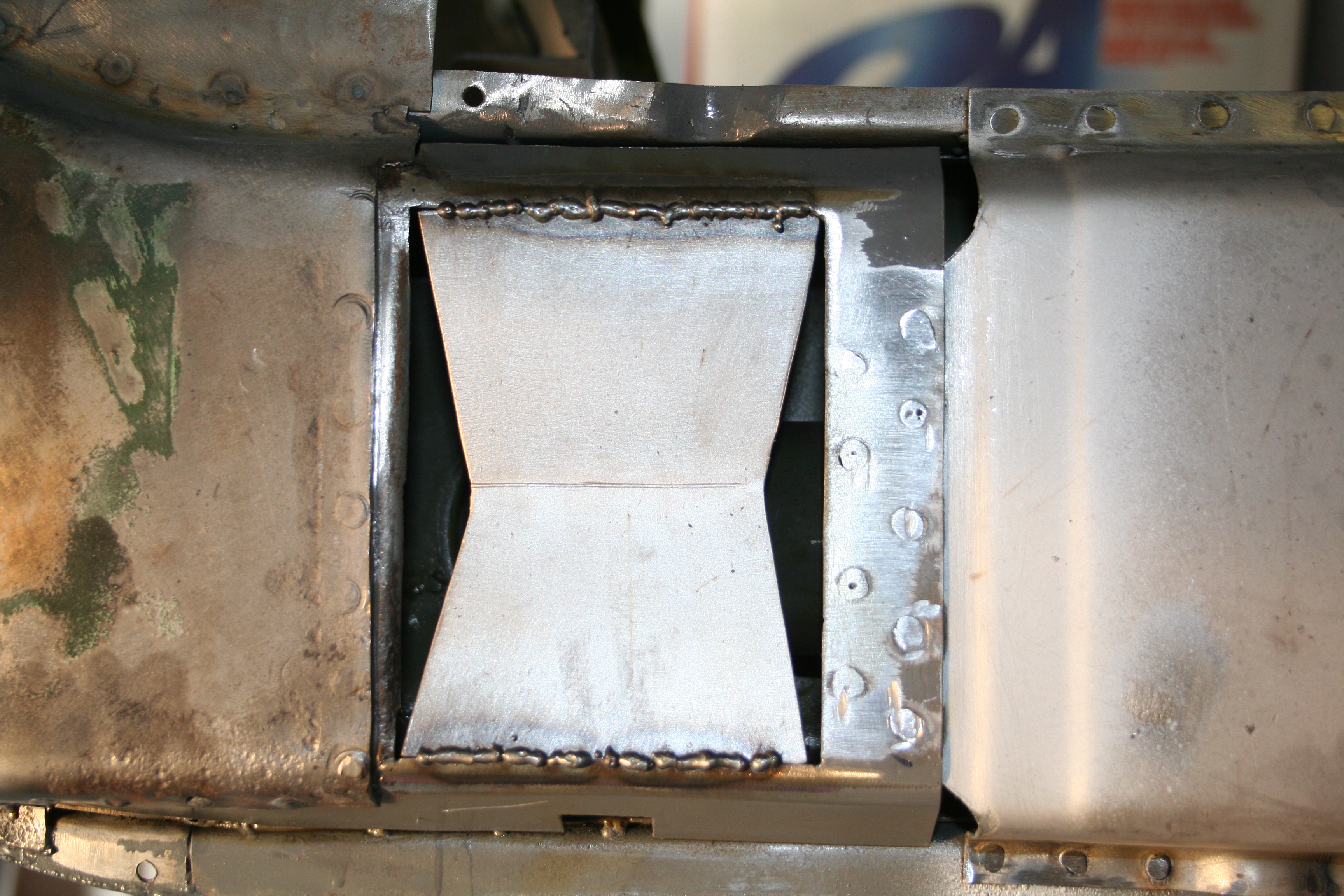
Here is an illustration of what I am trying to fix. The longitudinal is basically a box section created by spot welding to "U" shaped sections together. These U sections are either single walled, double walled or a combination of the two. In the area behind the jack receiver they are double walled both on the inner and outer U section. Battery acid and rain water has lain in the bottom of this section and rust through both the inner and out wall. Jacking up the car on this seam has resulted in the collapse of the bottom seam. This straight edge shows how much it has been pushed up. This shows how weak this section is.
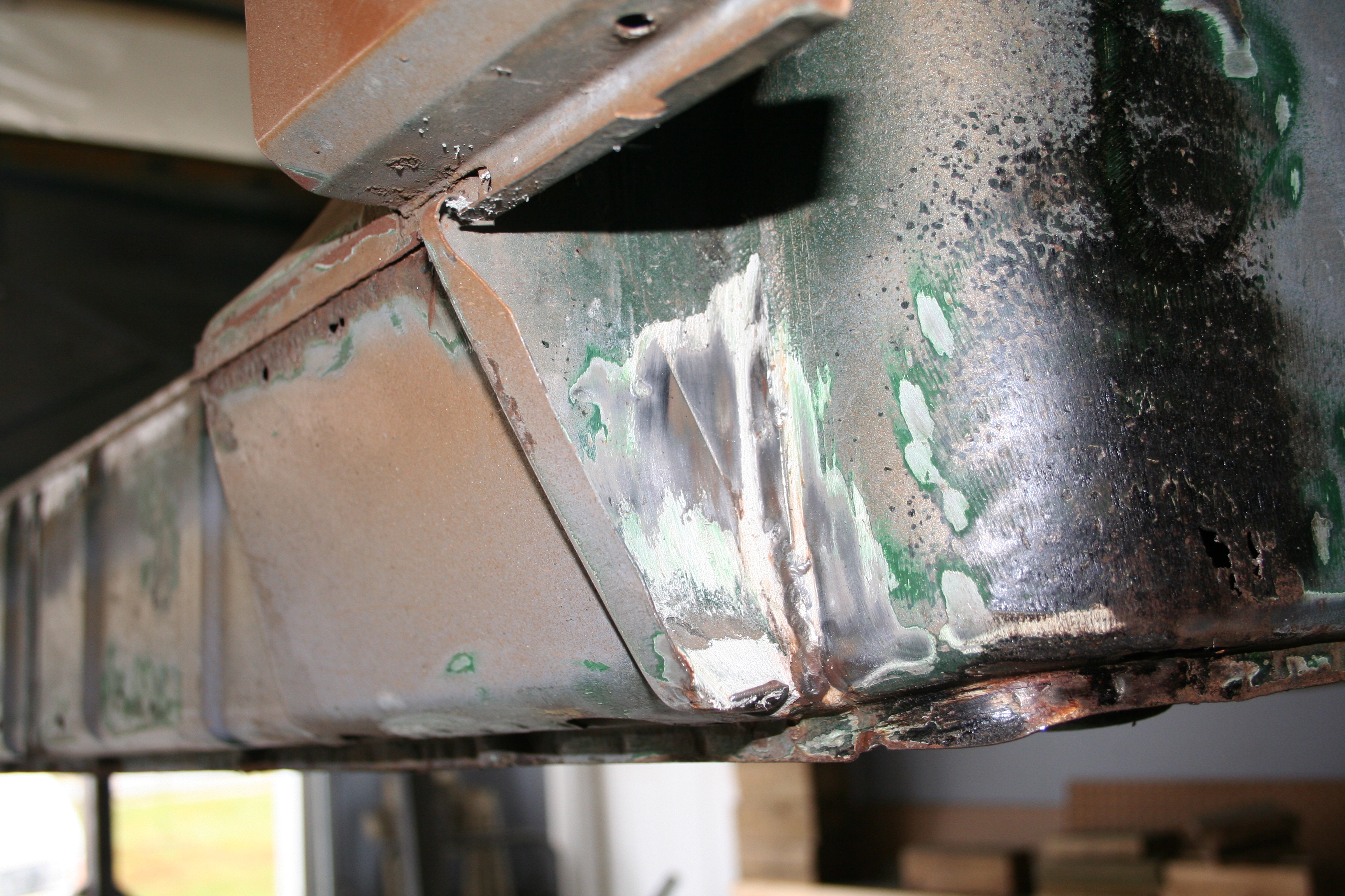
This is hard to to see, but this is looking inside the box section toward the rear suspension consoles. There is debris in here that is a result of the car doing 360 barrel rolls on the rotisserie. I have since vacuumed it out and the double wall in this section looks to be in good shape except for the very bottom near the jack receiver point. 11/4/2007Decided to work on the area at the front of the longitudinal. When I had cut into this area earlier, I wasn't sure how I was going to do this. Armando dug into this same area, so I am using a technique much like he shows here... http://www.pbase.com/9146gt/my9146gt_longitudinal_restoration_right Basically this is cutting through the layers, but to not overlap so that you can easily weld in replacements.
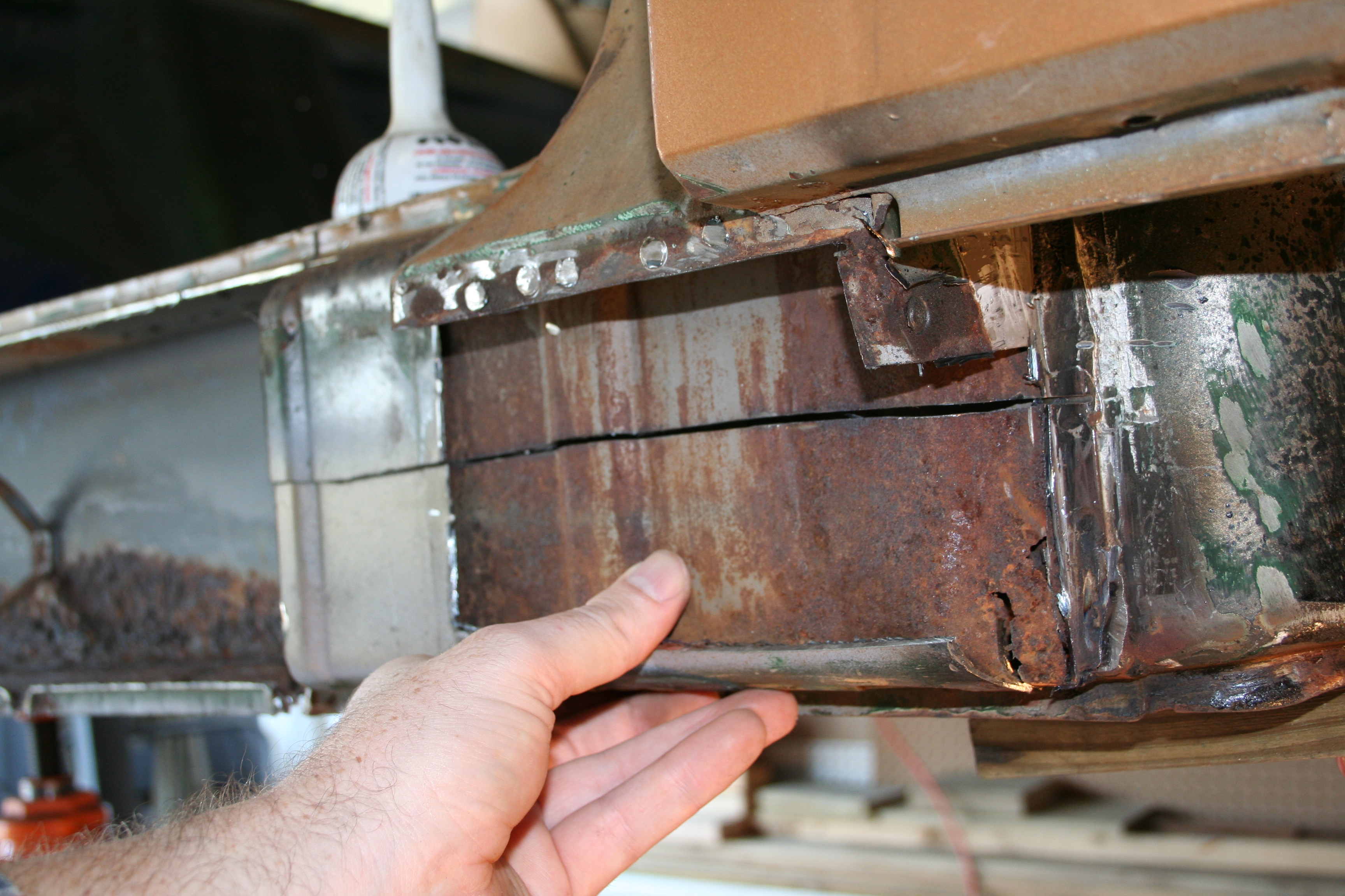
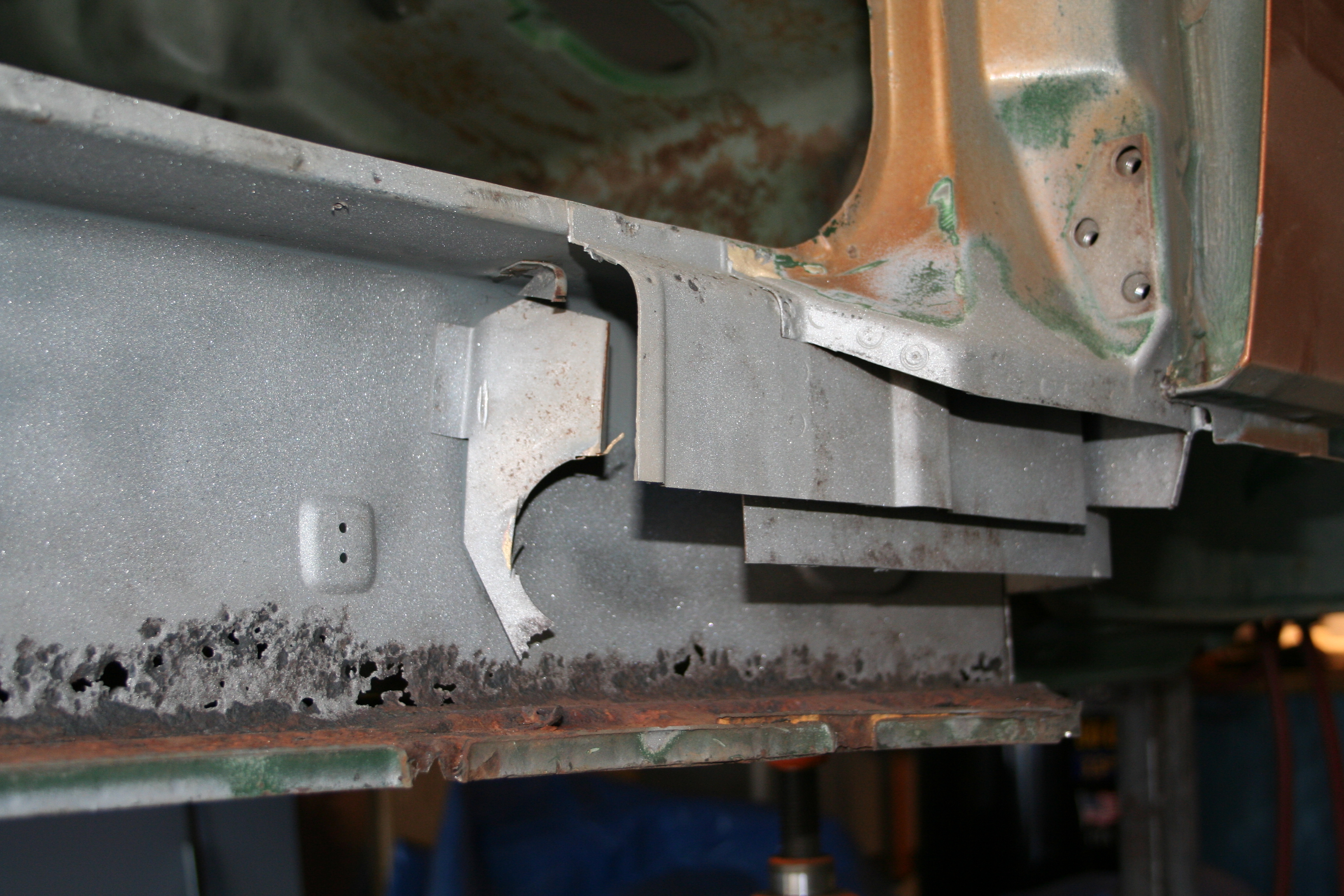
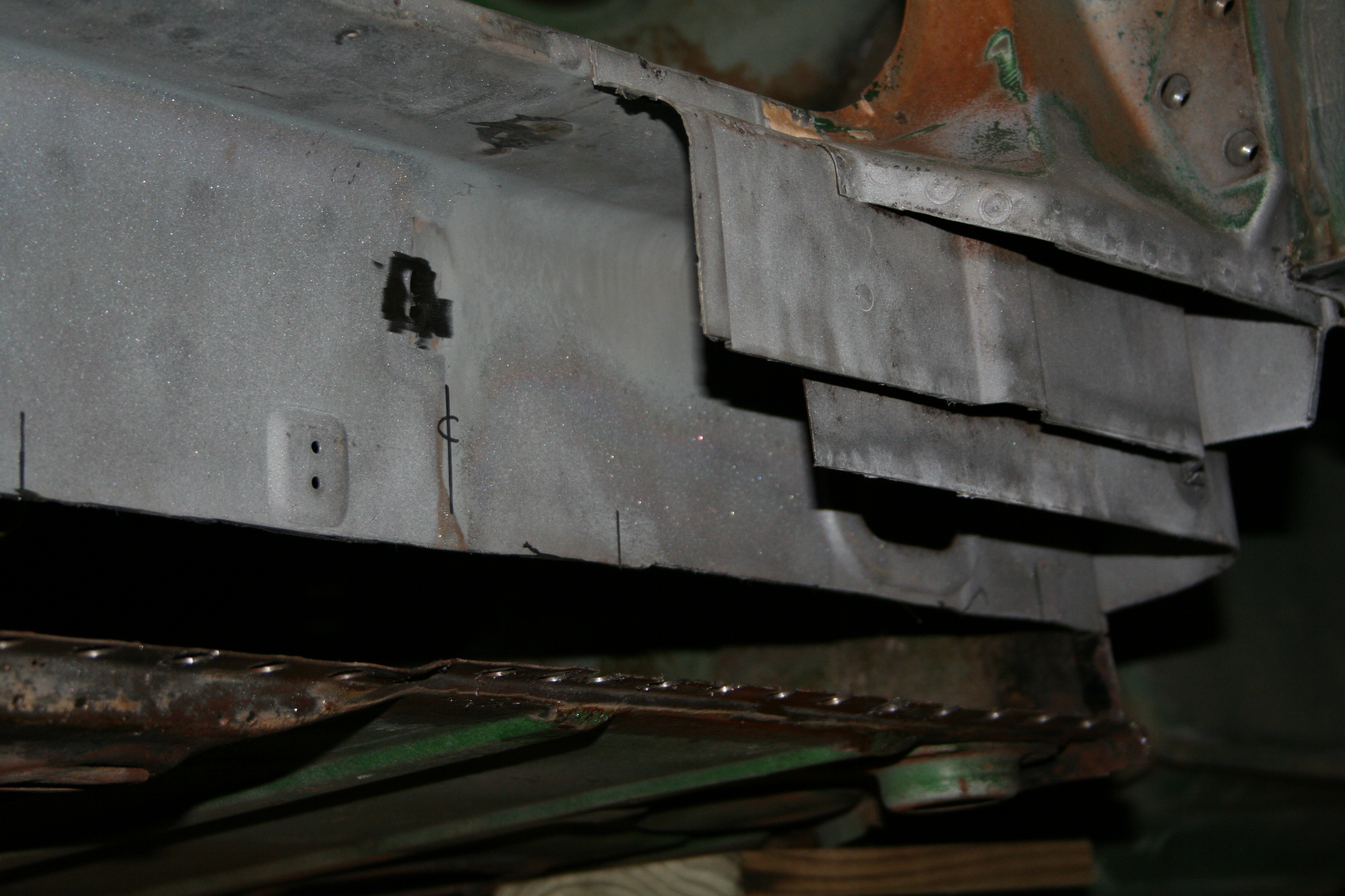
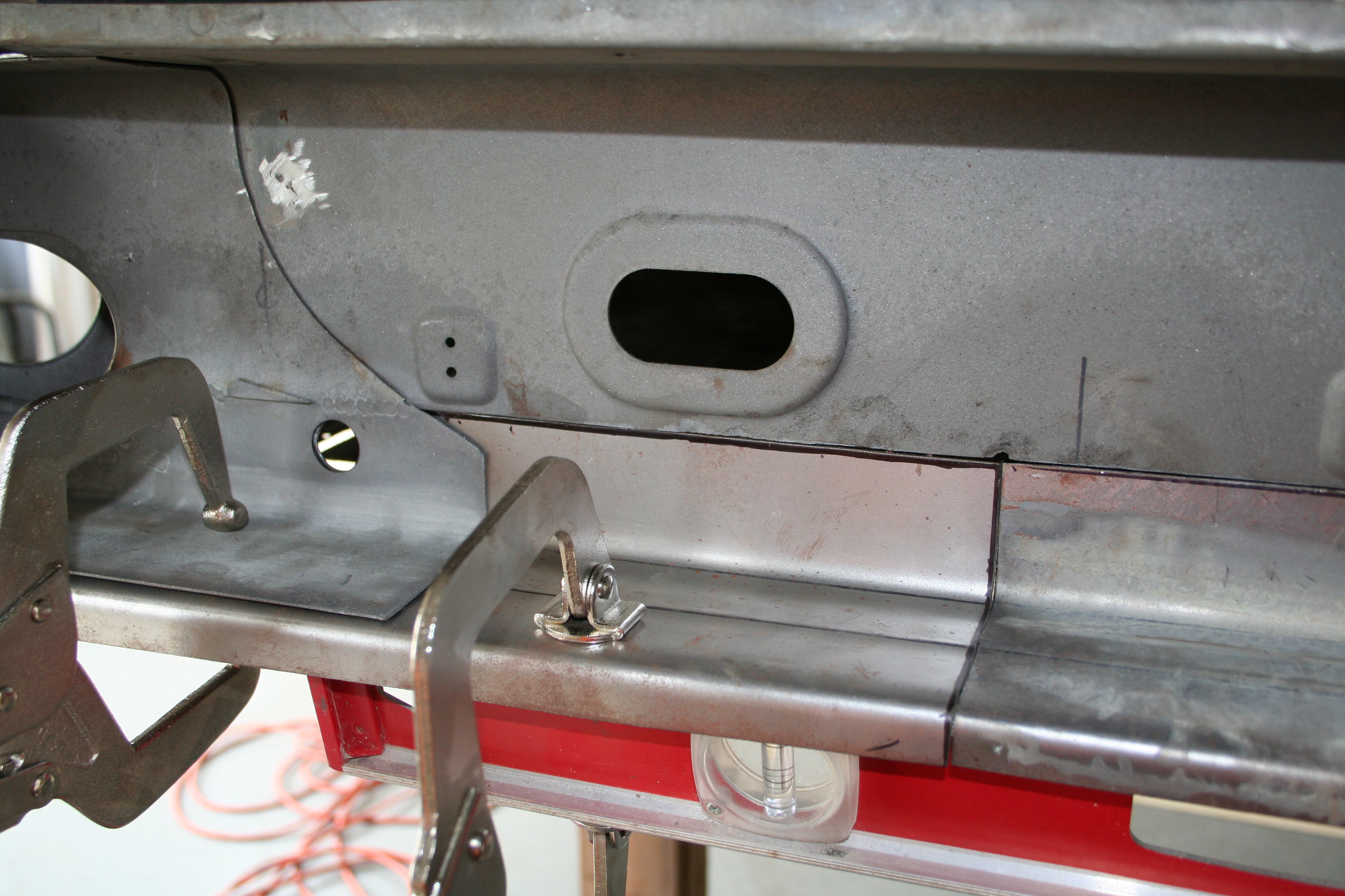
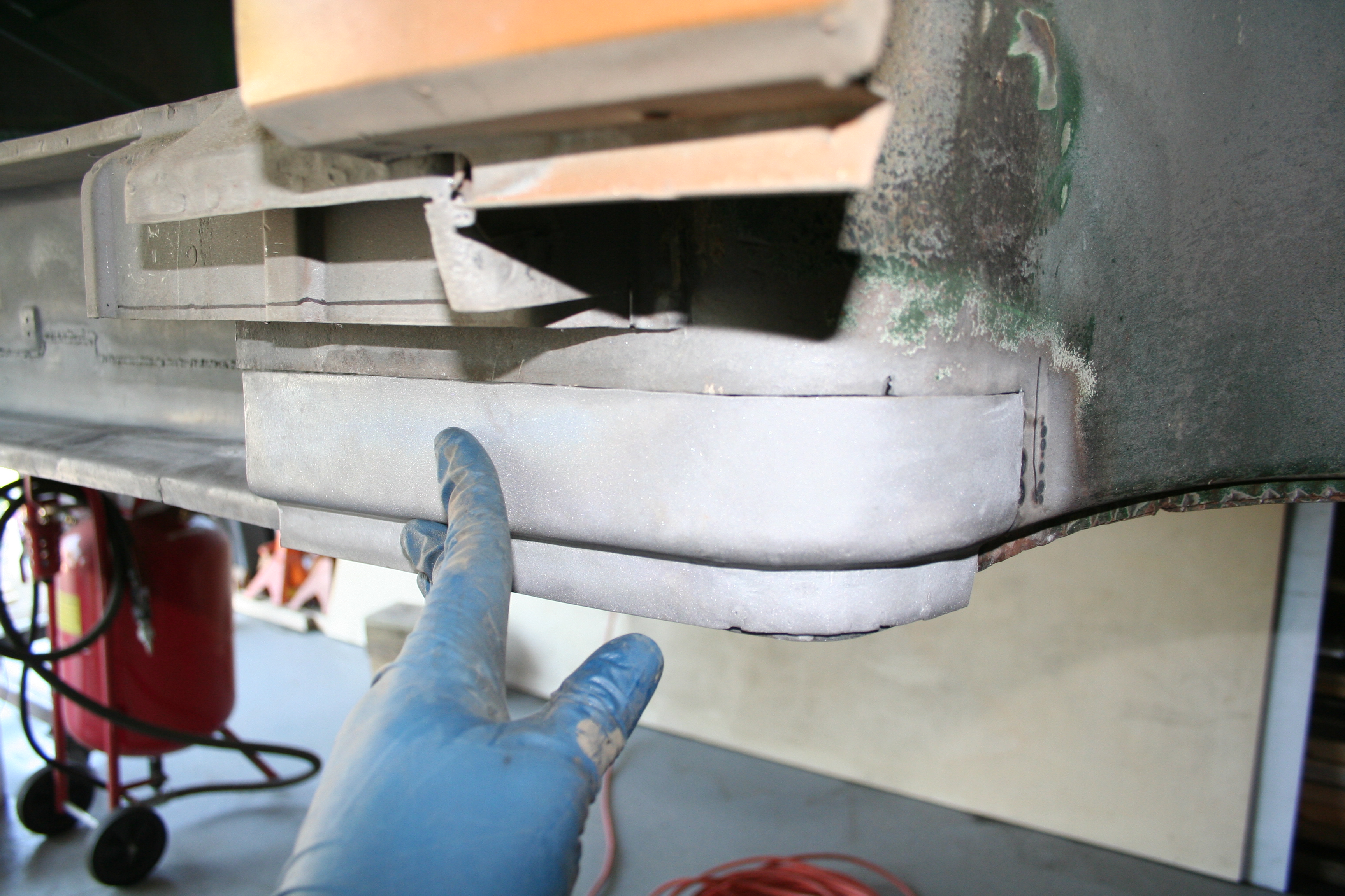
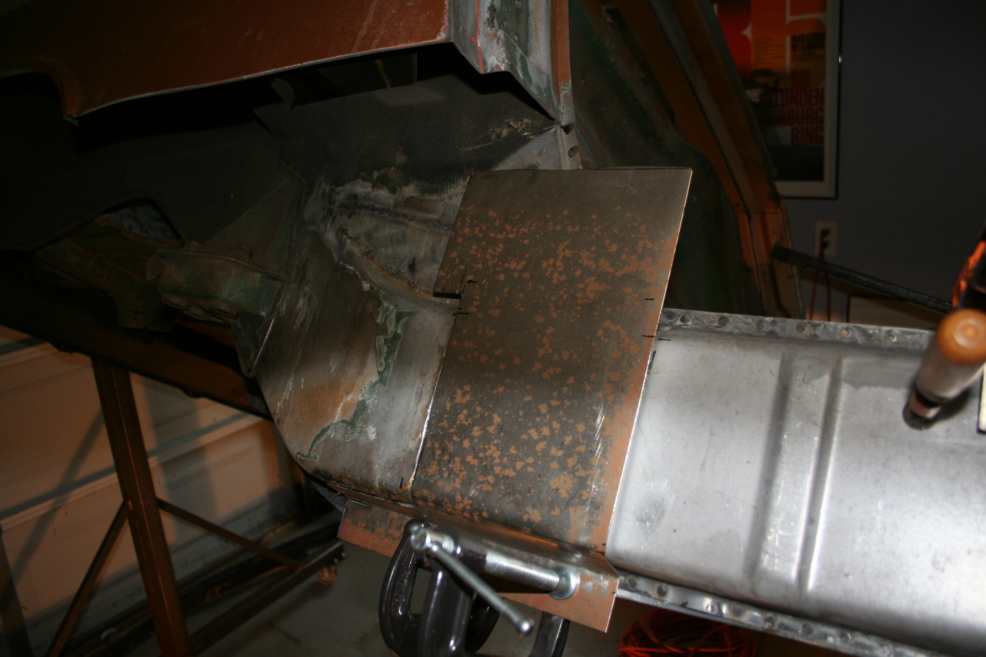
You can see it in a photo above (shot from same angle) but there was a small curved plate that is spot welded to the very front of this area. It is short of in the wheel well. I removed that via drilling out the spot welds and then cutting it at the top. I will clean up and well that part back in as is. Then I drilled out the reaming spot welds for what remained of the door sill in this area. Right below that was some rust. I cut horizontally right above the rust spots. This is where I will weld in the new outer plate. Below that plate is the outer longitudinal. In this photo, you can see that I have cut out the outer longitudinal, but only the bottom 1/2 in this section. This is done because the top 1/2 is in good shape and it buried behind another health panel. I would rather not tear out a lot of good metal here.
Here you can see that behind the outer longitudinal is another panel. There is a bit of an air gap behind the outer longitudinal before you get to this panel. The bottom of it needs to be replaced.
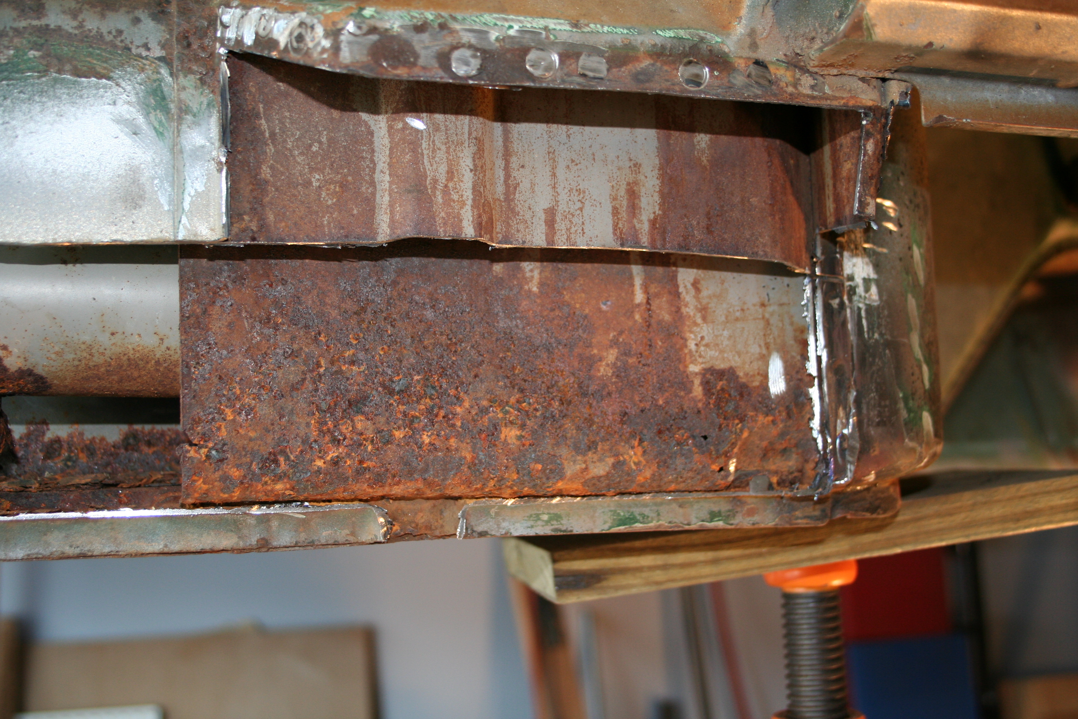
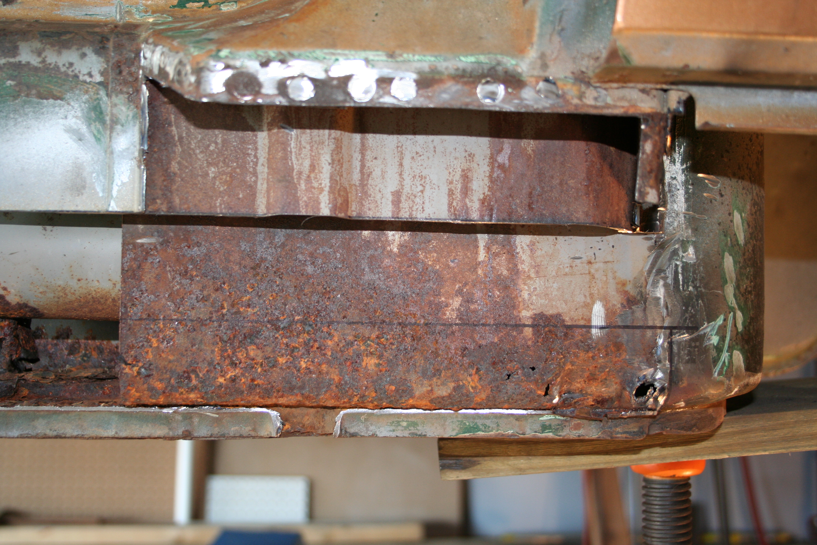
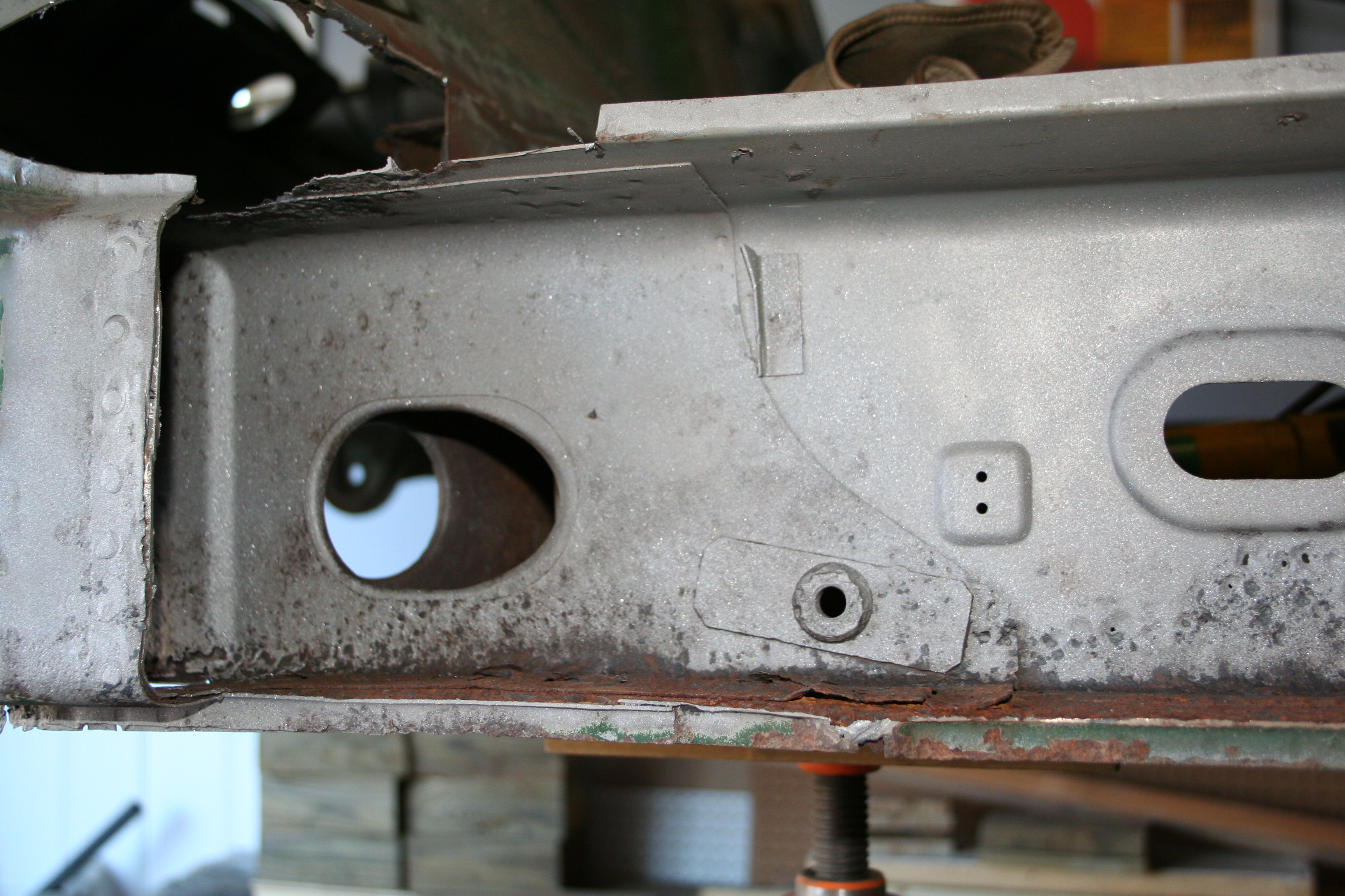
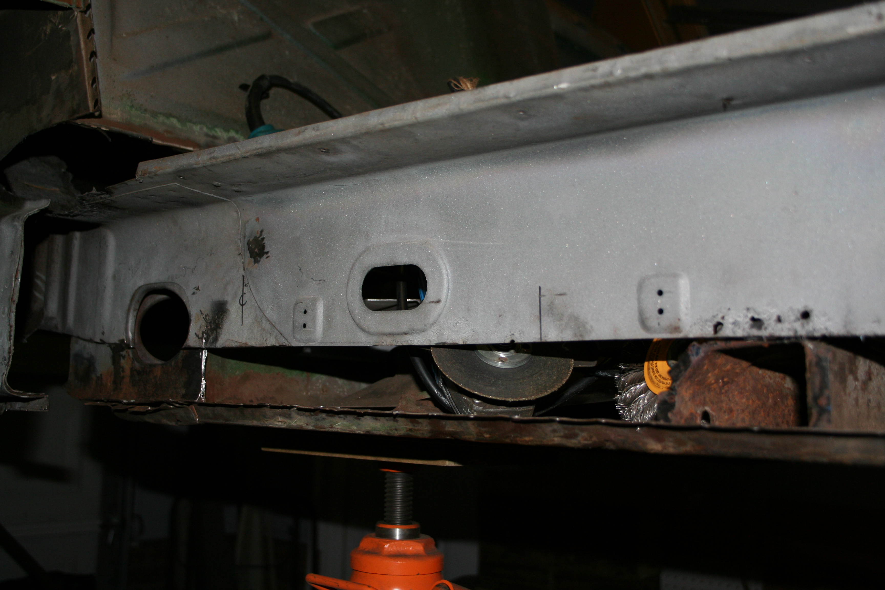
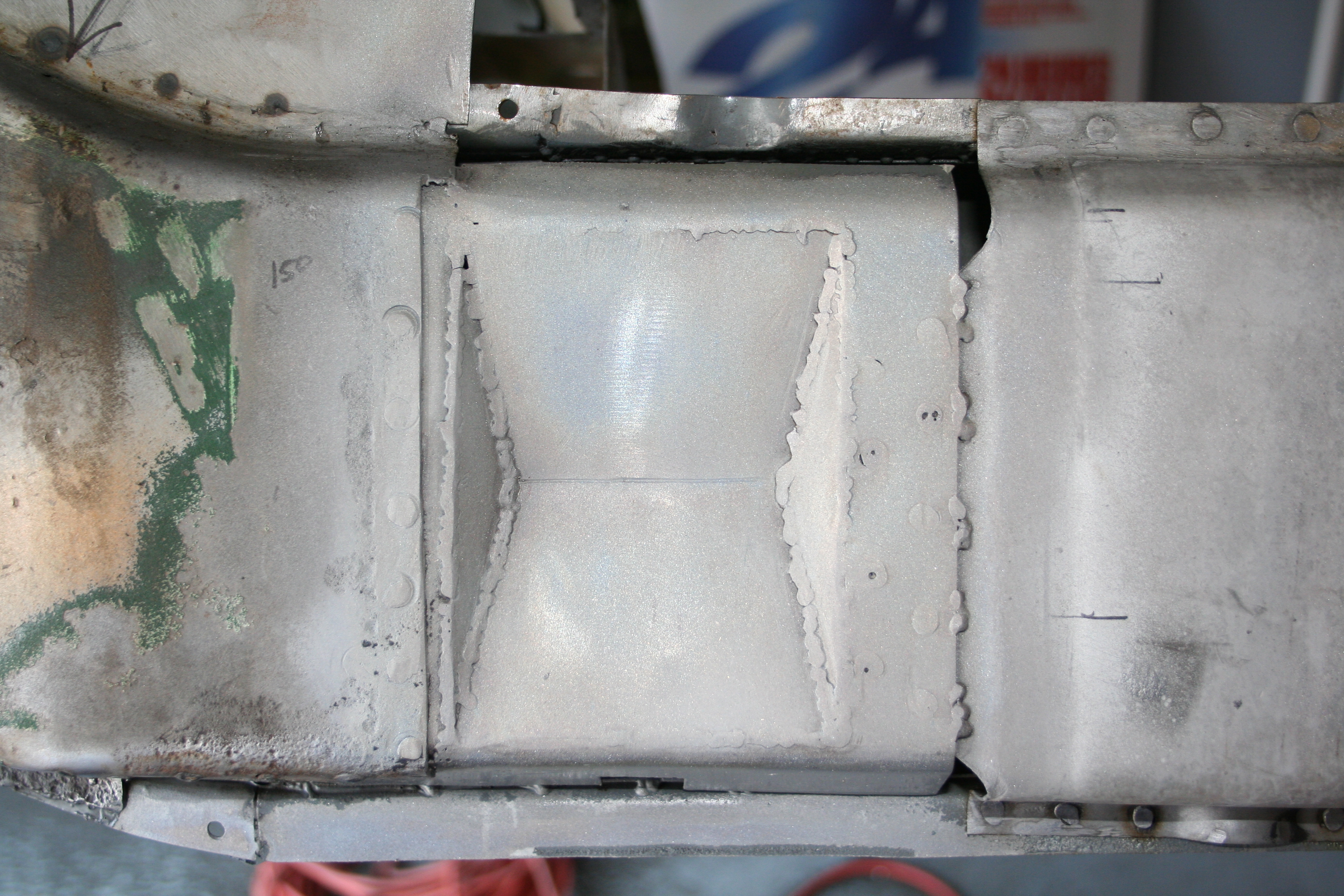
You can see my marked horizontal and vertical cut lines.
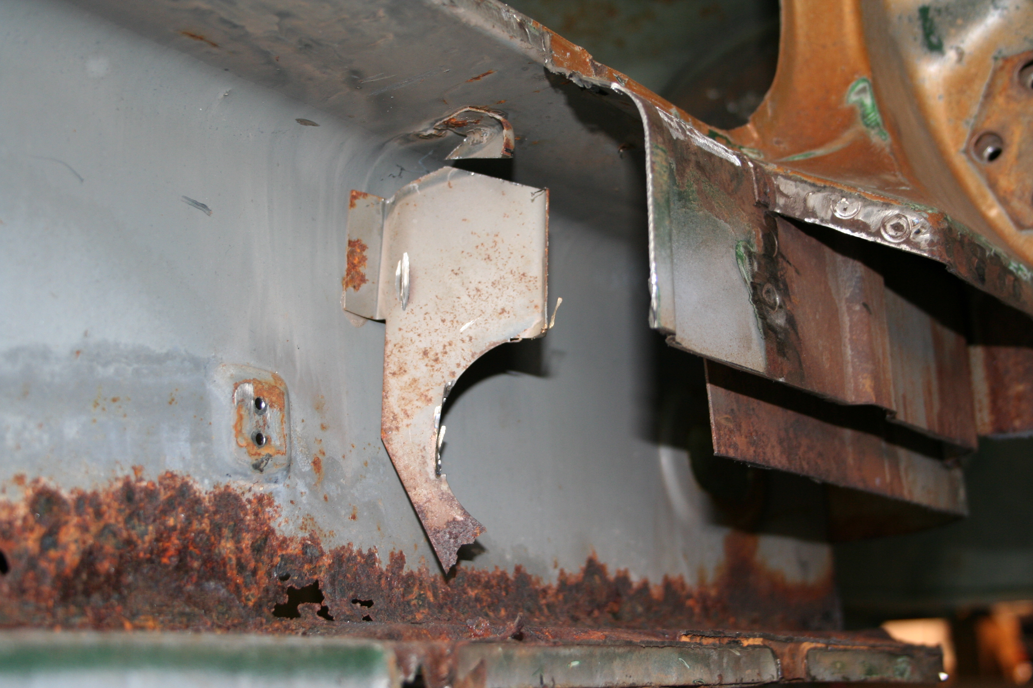
Here the bottom of the deepest panel is cut off. It just has some surface rust on it. It is otherwise health. This inner panel, the outer longitudinal and the cover panel are all three joined at the very bottom of the longitudinal. 12/2/2007To cut out the bottom on the inner longitudinal I need to remove the clips that hold the clamps that hold the flexible heater hose. Additionally I need to remove to two metal heater pipes at the front and the rear of the longitudinal. The clamps are really easy to remove as they are riveted in place and I just ground the rivet off from the inside. I plan to source similar replacement rivets. The pipes are a bit harder. These are attached in two places. Where they exit into the engine and passenger compartment, there are two small bead welds on each. Those need to be ground off and they are a total pain to reach. Those in the engine compartment are a bit easier, but those in the passenger compartment are in such a tight area that it is hard to get a grinder in. The end result is that the one in the passenger compartment was butchered a bit upon removal. The looks to be reasonably easy to repair, but I was pretty frustrated trying to get it out.
The second place these are attached are on a small bracket that it spot welded inside the longitudinal. In the photo above you can see that the bottom on these brackets have rusted away. As I am going to fabricate replacements, I didn't need to preserve these as well so they were cut out. I am saving the parts and have already put together a template for the replacement. While the bottom was rusted out, based upon the remains I think I know what they looked like. Interestingly enough the pipes look to have been brazed to these brackets. It is interesting to see where Porsche decided to spot welded, stick welded and brazed on the car.
Here you can see both clamps off and tubes out.
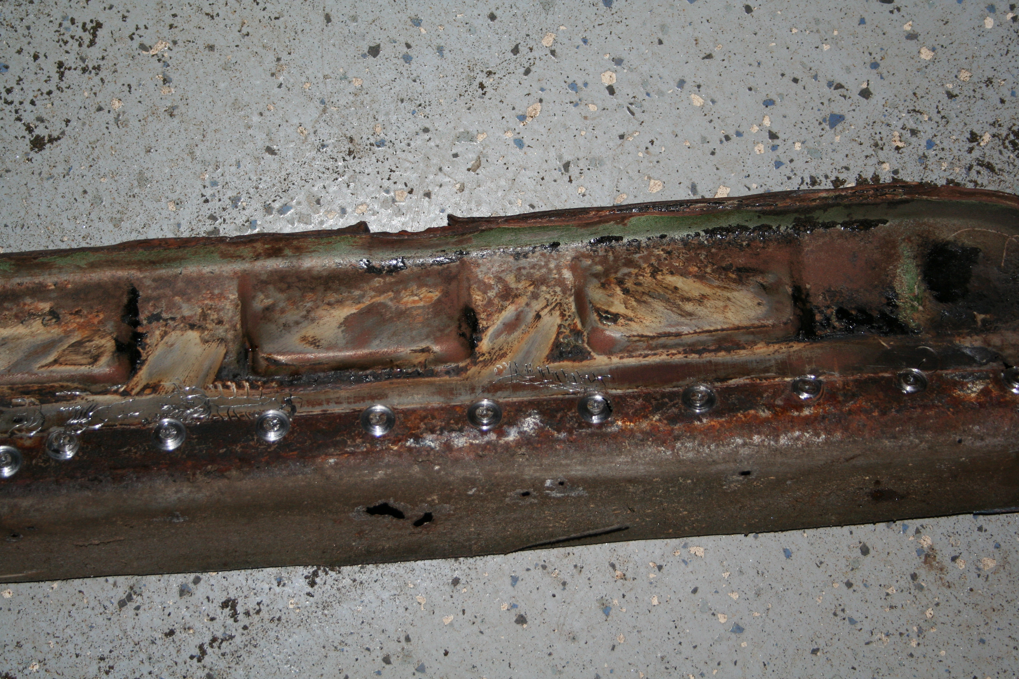
Close up of the rear. Note the double wall and reinforcement where the seatbelt attaches. You can also see the through hole where the heater pipe passes through the hollow bulkhead into the engine compartment. You can see part of where the rear bracket was spot welded on. Interestingly enough, when it was installed it was not spot welded on the top (bad work at the Karmann plant). I plan to do a better job when I put it back together.
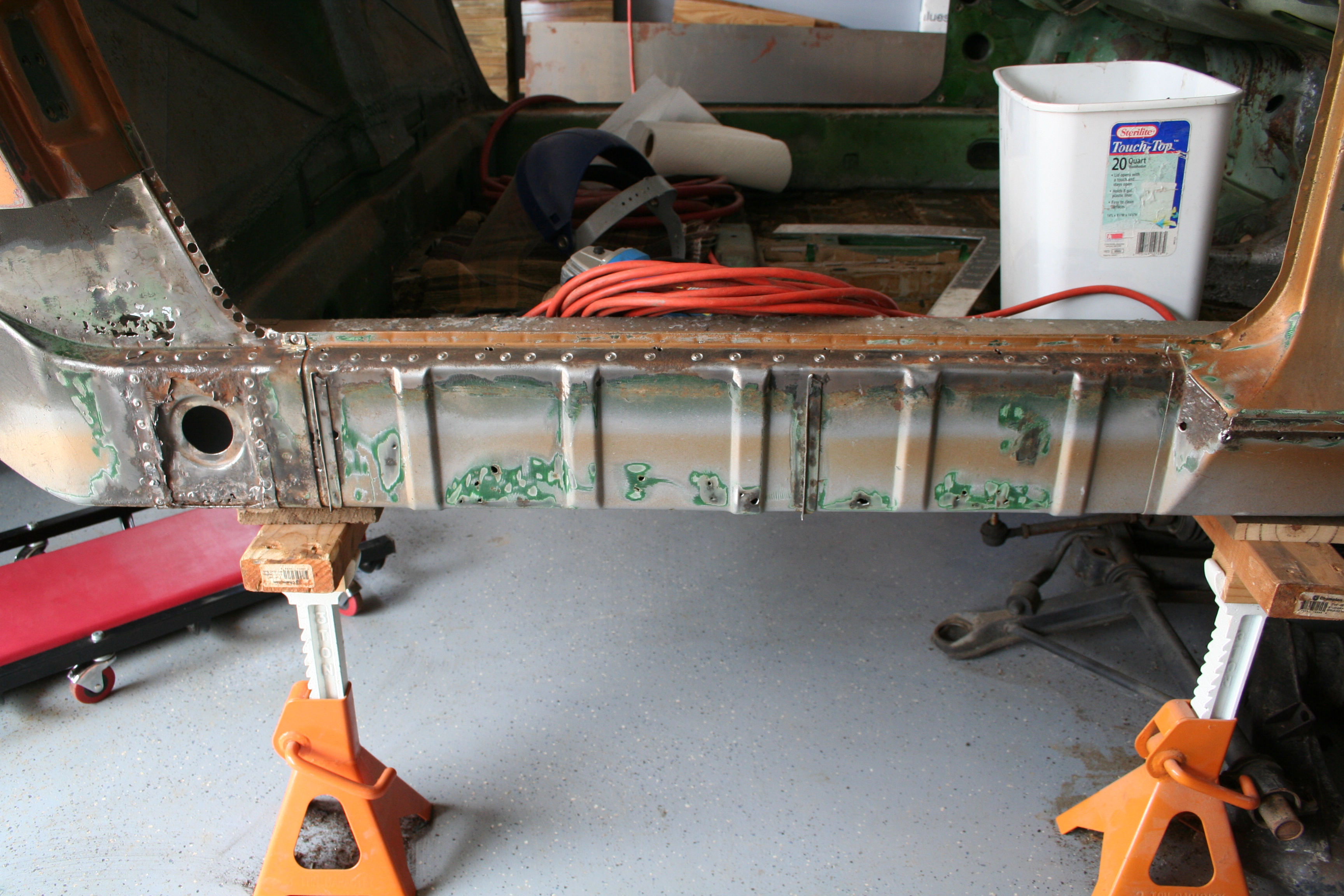
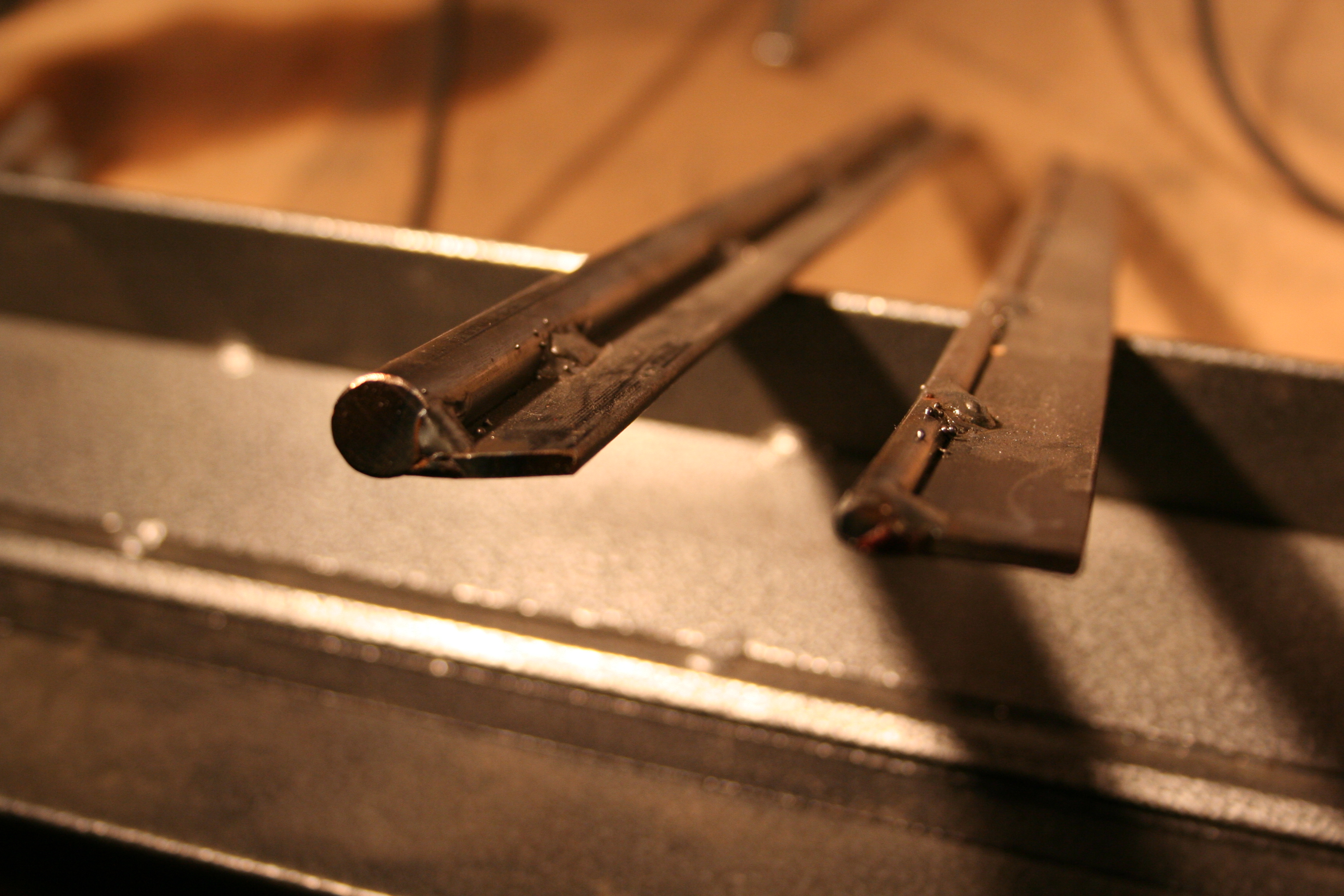
Here are the two pipes. Rear pipe on left and front on right. 12/24/2007I am at the point that I need to cut out the rusted inner longitudinal. I would prefer to make a straight and level cut from left to right, but I need to determine where the best place to cut. Exactly where does the rust stop. So I media blast the general area. I don't do much if any on the bottom (as it will be cut out), but I do find the edge of the good non-pitted metal. I will do final media blasting when I am ready to weld in the replacement parts. I sprayed everything down with Metal Ready to prevent flash rust from forming. I had some other areas that I did some trial media blasting and didn't spray with Metal Ready and they have since developed a light flash rust surface.
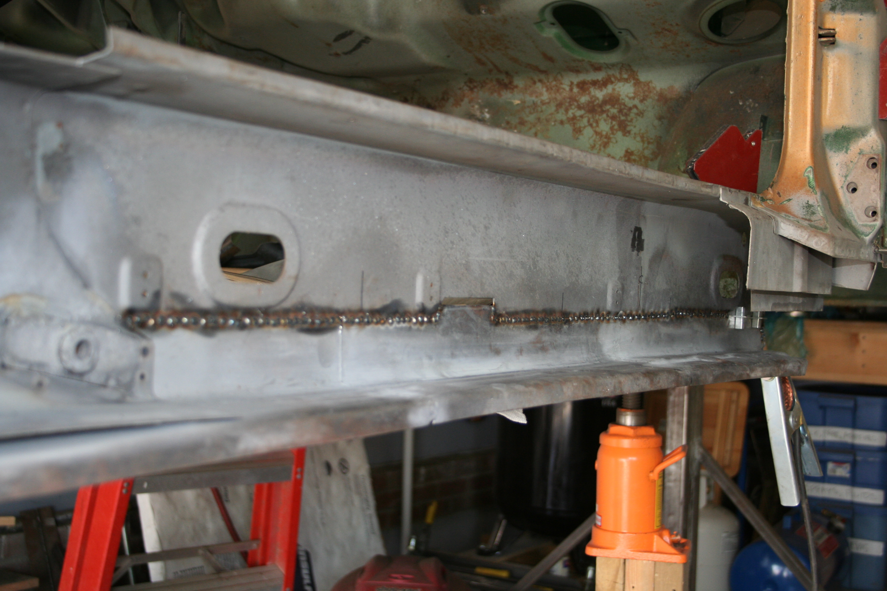
12/29/2007One last thing to do before I cut out the passenger inner longitudinal. I need to drill out the spot welds that attach the floor to the longitudinal.
I use a Blair Rotabroach 3/8" spot weld bit. As long as you use a center punch to get a pilot dimple in the center of the spot weld and use cutting oil it does a great job.
I settled on a horizontal line just below the dimple for where the hose clamp is attached. That keeps most of the bad metal below the line and just a few places above it. Those above are in the area around where the left/right box section (that the front of the seats mount to) intersects with the inner longitudinal. That box section seems to be a rust trap. I will probably replace the metal higher up on the inner longitudinal in that area. 12/30/2007While the photos below were shot tonight, this was actually the rest of the work done yesterday. I removed the rusted bottom section of the inner longitudinal.
You can see the whitish color of the metal after the Metal Ready treatment. I put in some vertical marks along the cut line as registration points that I can transfer over the the new section I am going to fabricate. You can also see that I ground off the remains of the brackets that held in the heater pipes. I did mark the center line of each bracket so I can tell where to put the replacements. The flanges on the brackets face inward. The two brakes are not identical, but they may be mirror images of each other?
As I was cutting this, I had originally planned on removing the section below the heater pipe through hole. However that metal has surface rust only and I decided to leave it in place. I have some intrusive cuts that need to be welded up, but I have a handful of these that I need to just weld up and grind down. I am currently planning on salvaging the special seat belt bold and it's attached backing plate that is on the part that I cut out.
While in general the section I cut out is basically an "L" it has some intricate corrugation along the bottom that I am going to try to replicate. The current plan is the fold the "L" on my sheet metal brake and then hammer form the corrugation. I probably will do a short test section first before I tackle the entire section. I also suspect I may need to do this entire part in at least two sections as the front 1/3 is different enough from the rear that it may be easier to fabricate them separately and then weld them together. I am so close to fabricating the replacement parts that I can taste it. But most likely I will continue to cut out and clean up this and the "Hell Hole" area before I fabricate any parts. 2/6/2008 - 2/7/2008I am ready to start fabricating replacement part! So I bought the
following book awhile back... "Sheet Metal Handbook: How to Form and Shape Sheet Metal for Competition, Custom and Restoration Use" by Ron Fournier http://www.amazon.com/Sheet-Metal-Handbook-Competition-Restoration/dp/0895867575 It supposedly is one of "the" books you need to buy if you want to learn how to form sheet metal. The techniques I decided to use was bending with a metal brake and hammer forming. I bought a small metal brake and other metal forming tools from Harbor Freight.
First thing was to create some curved forms so that I could bend with specific radius on the metal brake. This is because much of the bend on what I am reproducing is not hard 90 degree bends, but rather something with a handful of millimeter radius. These consist of a few rods of mild steel welded to a long plate. These can then be clamped down along with the metal in the brake and then the bend is folded around them.
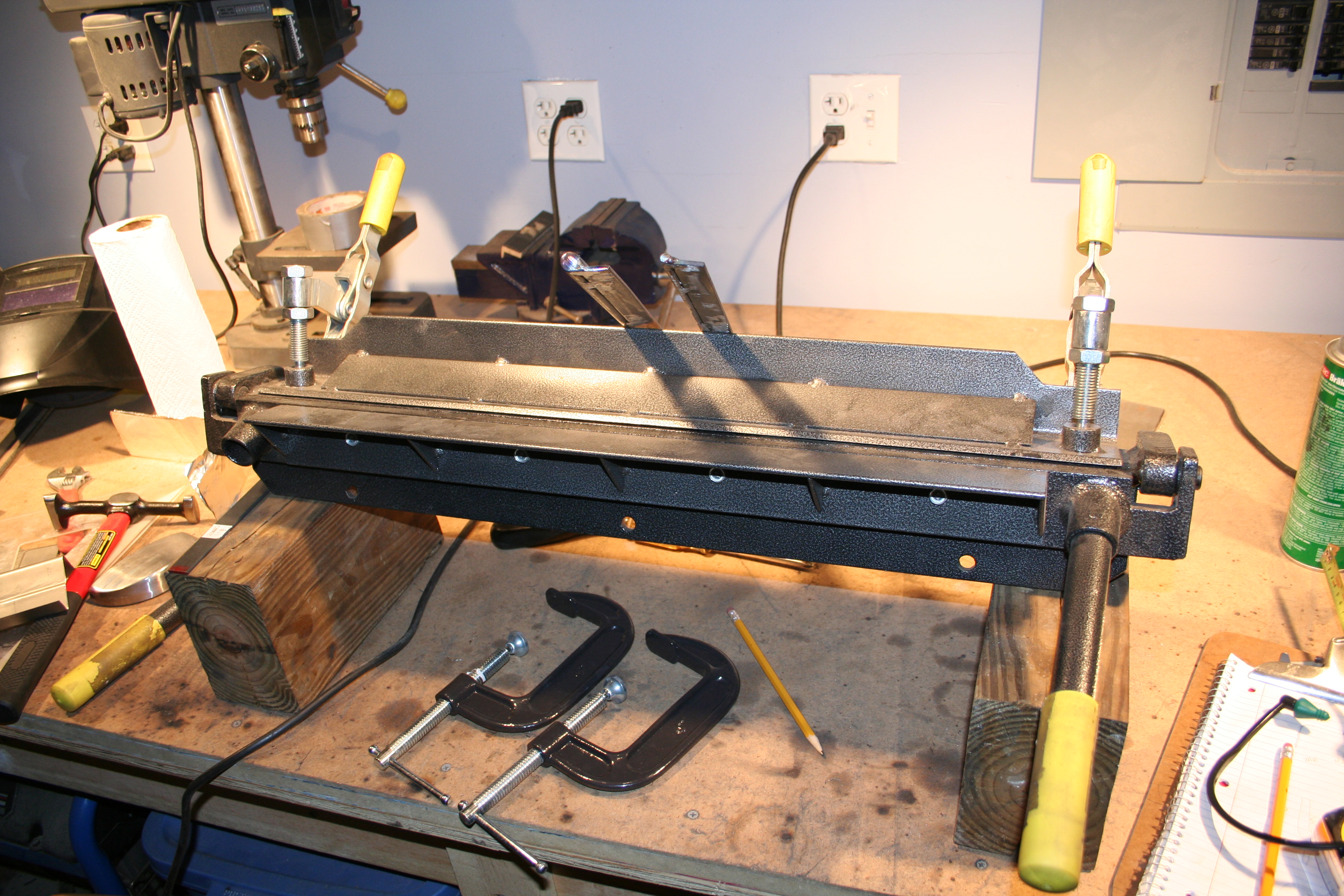
Here is the brake. I am too lazy to mount it to the table.
I did a quick few bends with some thinner 22 gauge metal just to verify that I could get the basic bends in place. This piece is not dimensionally correct.
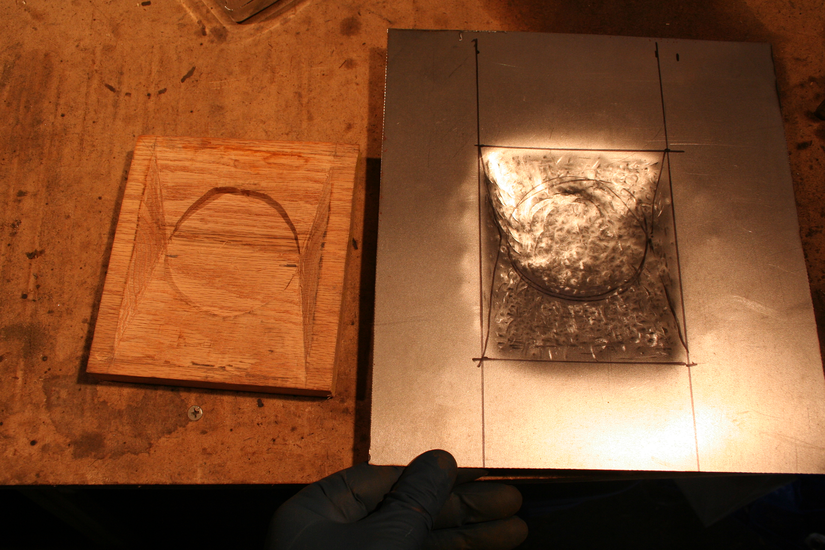
On the part I am reproducing there are some areas that I need to hammer form. This means I create a mold that I will hammer the metal into. I cut small sections from a bar, grinded them to the proper shape and then welded them onto another flat plate.
I then was able to place the metal over the form and hammer it into the void between the two parts I had welded onto the plate. It is not exactly easy to see in the photo above, but the part cut from the car shows the small channel that I am reproducing. In my test run, I probably made the channel too deep, but I am not make it as deep with my real part.
Based upon how the test part worked, I marked out my dimensions on the real part.
Here is the real part laying on top of the part cut from the car. 4/26/2008Ok, now I am moving forward and need to double wall the section behind part of the new skin I just created around the suspension console/motor mount area. I have not welded on the skin yet.
Test fit from the inside. It is a total pain to weld on the inside.
On the left is the part that will double wall the section I am working on above. The one on the right is the double wall section that is part of the passenger longitudinal. The big hole is where the seatbelt mount passes through. I have sprayed on a weld through primer.
Here I have welded in those two sections. I have not yet ground down the welds in this photo.
My weekend office! 6/22/2008I have been busy working, but not many photos the past few months. The items above were fabricated with 20g steel and I realized that I really need 18g. So I bought some 18g and recreated the items above. I don't know why I didn't take more photos of the middle steps. Particularly the front section that is curved. I used a wooden form to help me hammer form this. Also the entire section is three segments welded together. I did this for two reasons. First my metal brake is not wide enough and second there is a slightly different shape for the first third. So even if my brake was large enough, I would have had to join to sections together anyhow. Photos below are very late in the process.
Here I am marking the back half so I can tell where to trim so I can butt weld the two halves. I am using the level as a straight edge.
You can see I have cleaned up the new section on the left that the set belt mounting point passes through. You can see it is marked for final trim.
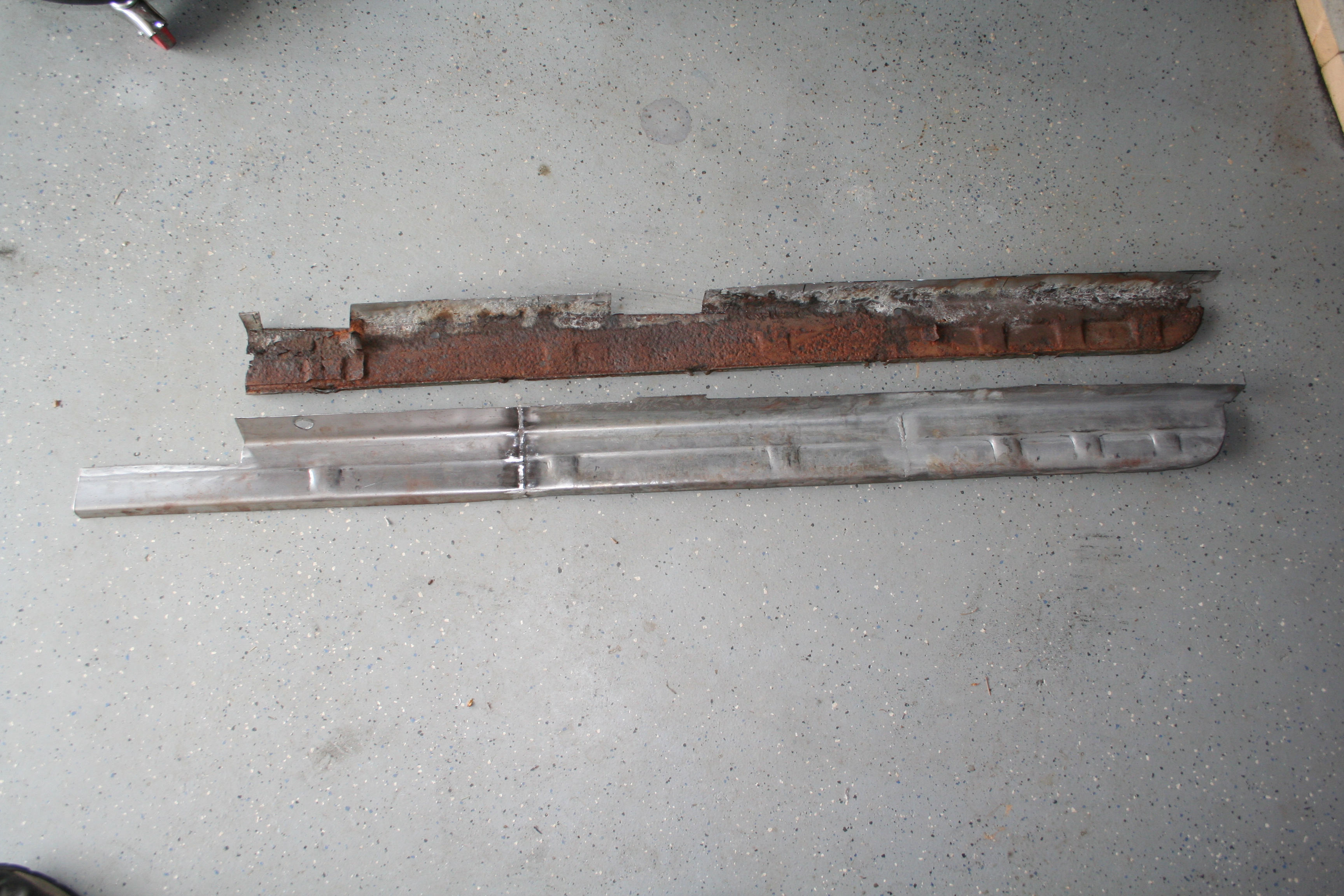
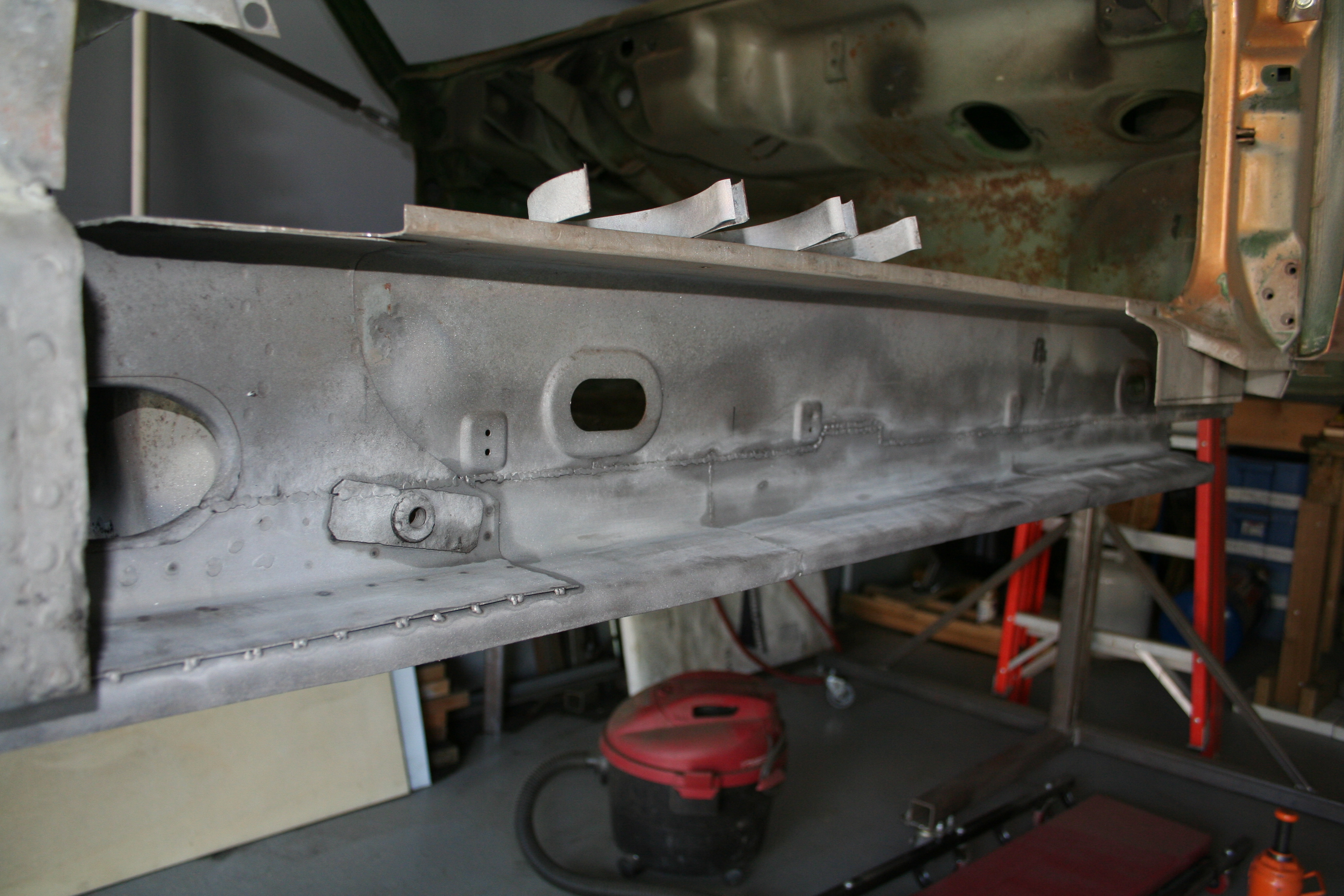
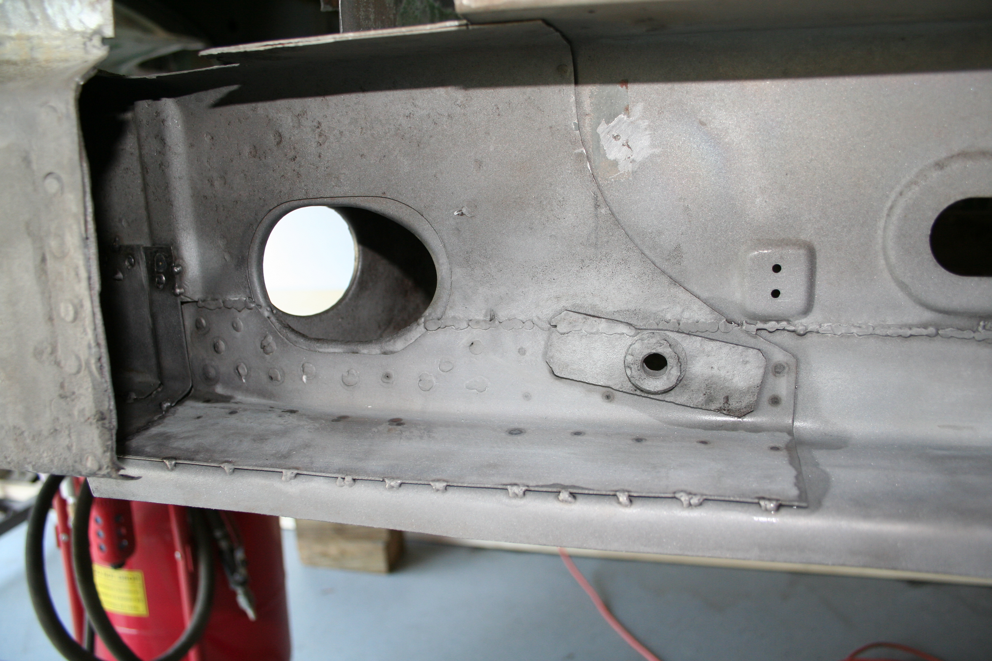
Here is the final product next to the old rusted segment. Items of note is that in this view, you are seeing the inside of the longitudinal. So the welds between the sections are not ground flush as they are never to be seen. You can see the curve for the front section. You can see how the front third ramps up a bit. You can see the indentations that match the original part. You can see the hole drilled to allow the seat belt mount to pass through. This section is double walled. The part above is just one part and in the photo above (already welded to the car) is the inner double wall section. In the photo above, I have not yet welded the seatbelt mount back into place.
Here is the view but of the bottom. The welds are more flush here as you will be able to see these if you crawl under the car. Overall the part of fun to make, but I really wish someone made an inner longitudinal section. I think it is common for the bottom half to rust out. I think that many people just weld in an "Engman" longitudinal kit to fix this area. There is nothing wrong with that, but I wanted to keep the stock look with a semi-exact replacement part.
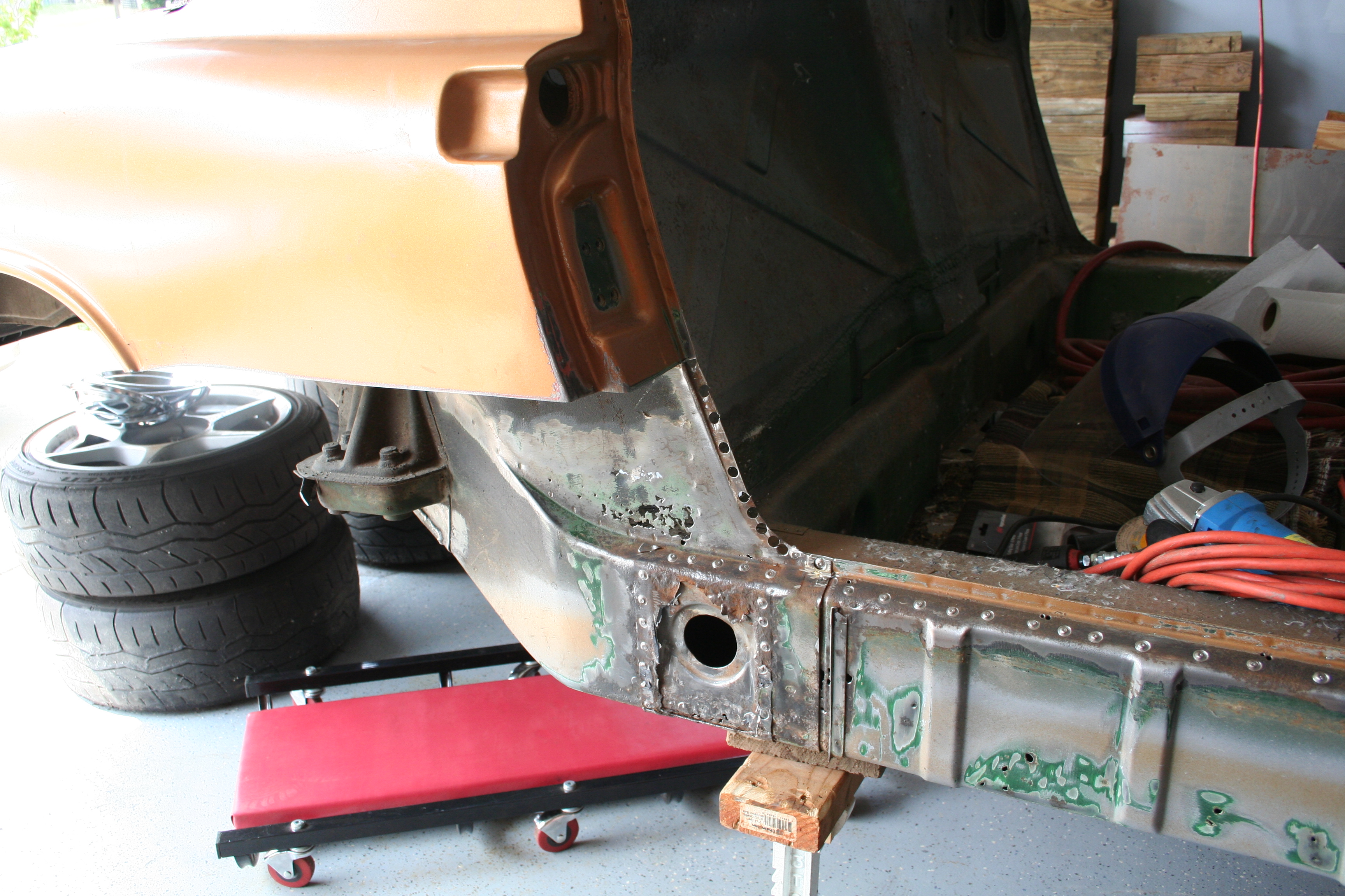
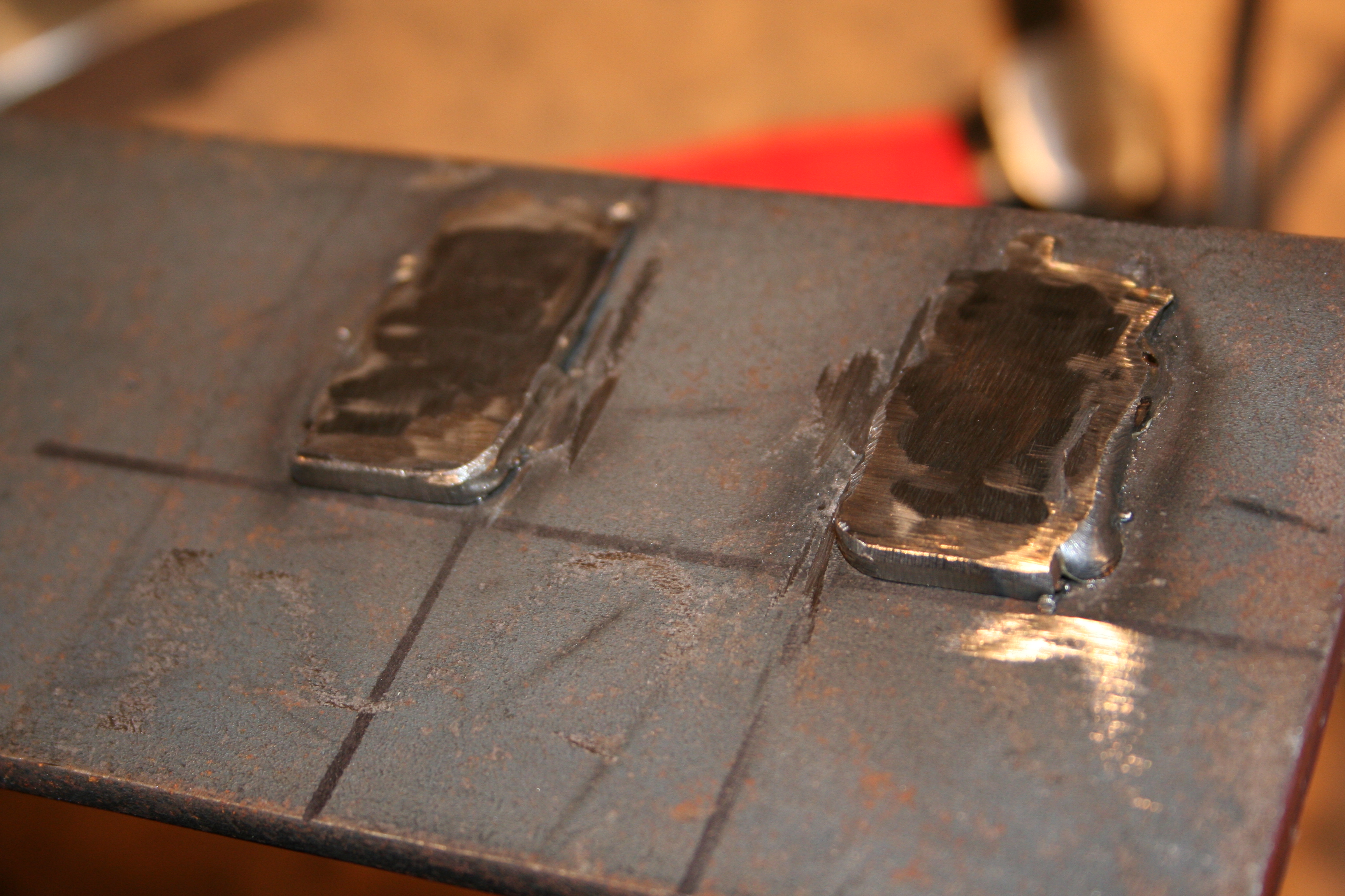
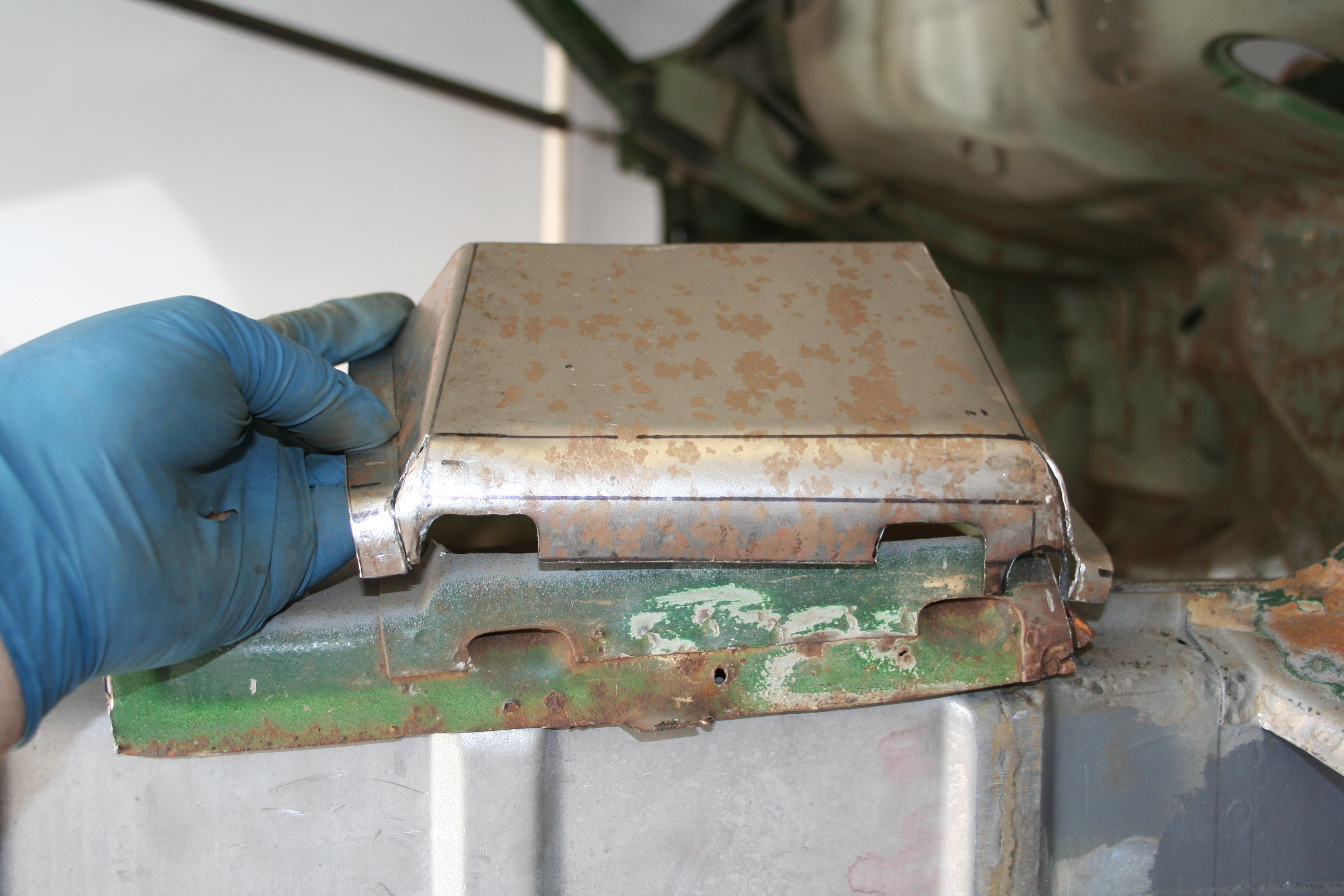
7/14/2008 - 7/18/2008I took the entire week off from work and worked half of each day on the car. My goal was to get to the point that I weld on the outside of the longitudinal. but I didn't quite get that far. Before photos of the heat tubes. I need to grind off the remnants of the bracket that hold the ends to the inside. I also butchered part of the tube that is in the passenger compartment. It was a bear to grind the welds in that area to remove it. So I had to patch up those holes. I mostly just wanted to document the location of the brackets. Those are brazed on at the factory instead of welded.
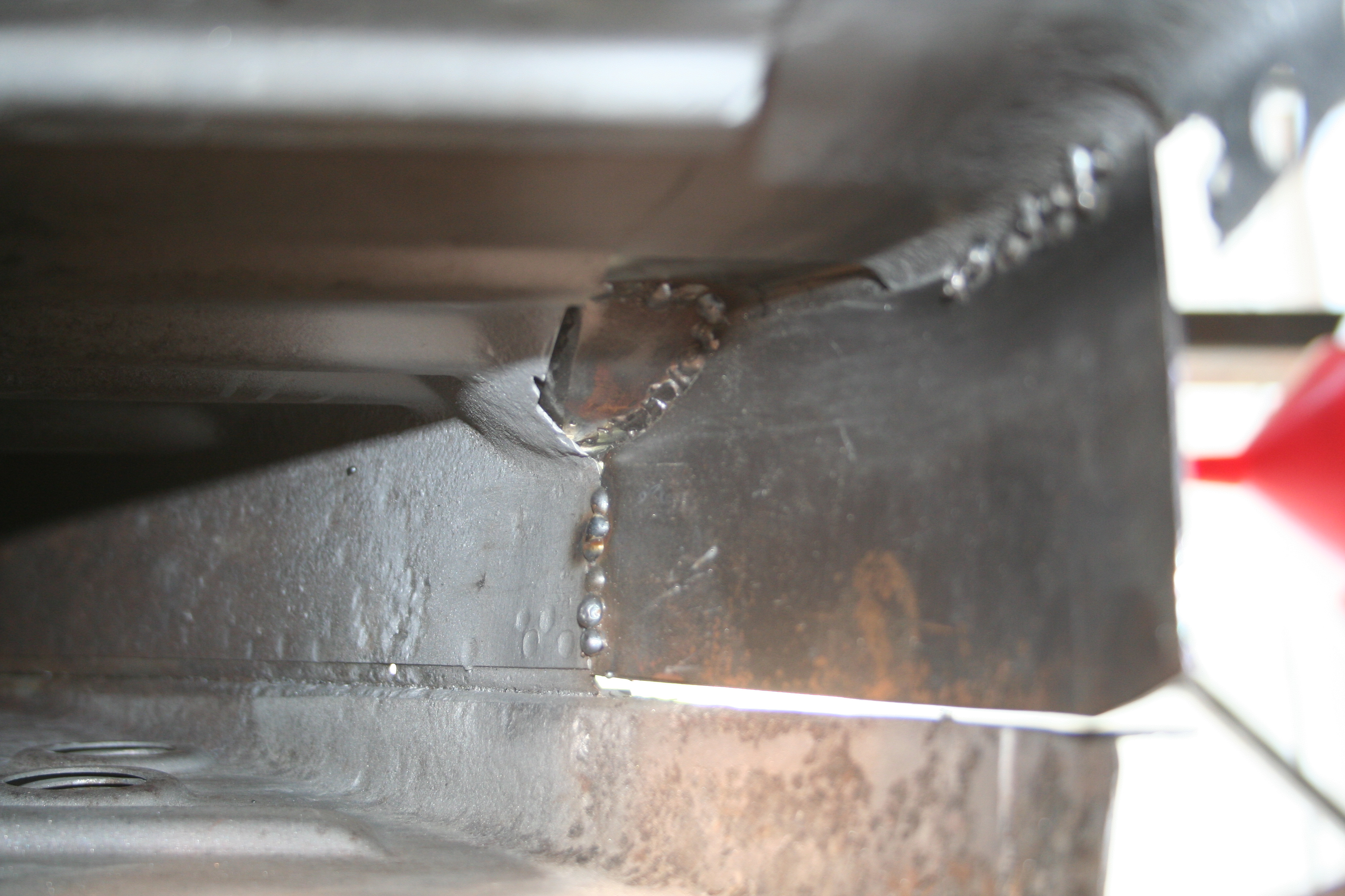
Here I have welded in the replacement. To butt weld this type of sheet metal, you can't lay a continuous weld, but rather very short welds and many of them. This is to reduce heat and ultimately burning through the good metal.
By this point the car is strong enough that I have taken the jacks out from under the bottom and have rotated it on the rotisserie. I did this so I would not have to weld out of position. Another problem with sheet metal is warping and bending due to the weld tightening up as it cools.
Rosette welds in holes that I drilled into the new part. You can see the passenger seat belt mount point here.
Pretty much finished. I grinded down the inside welds just a bit to dress them up. No need to try to grind them down all of the way as they will not be seen. I then media blasted and then sprayed with Metal Ready. It really works and prevents rust.
More of same.
More of same.
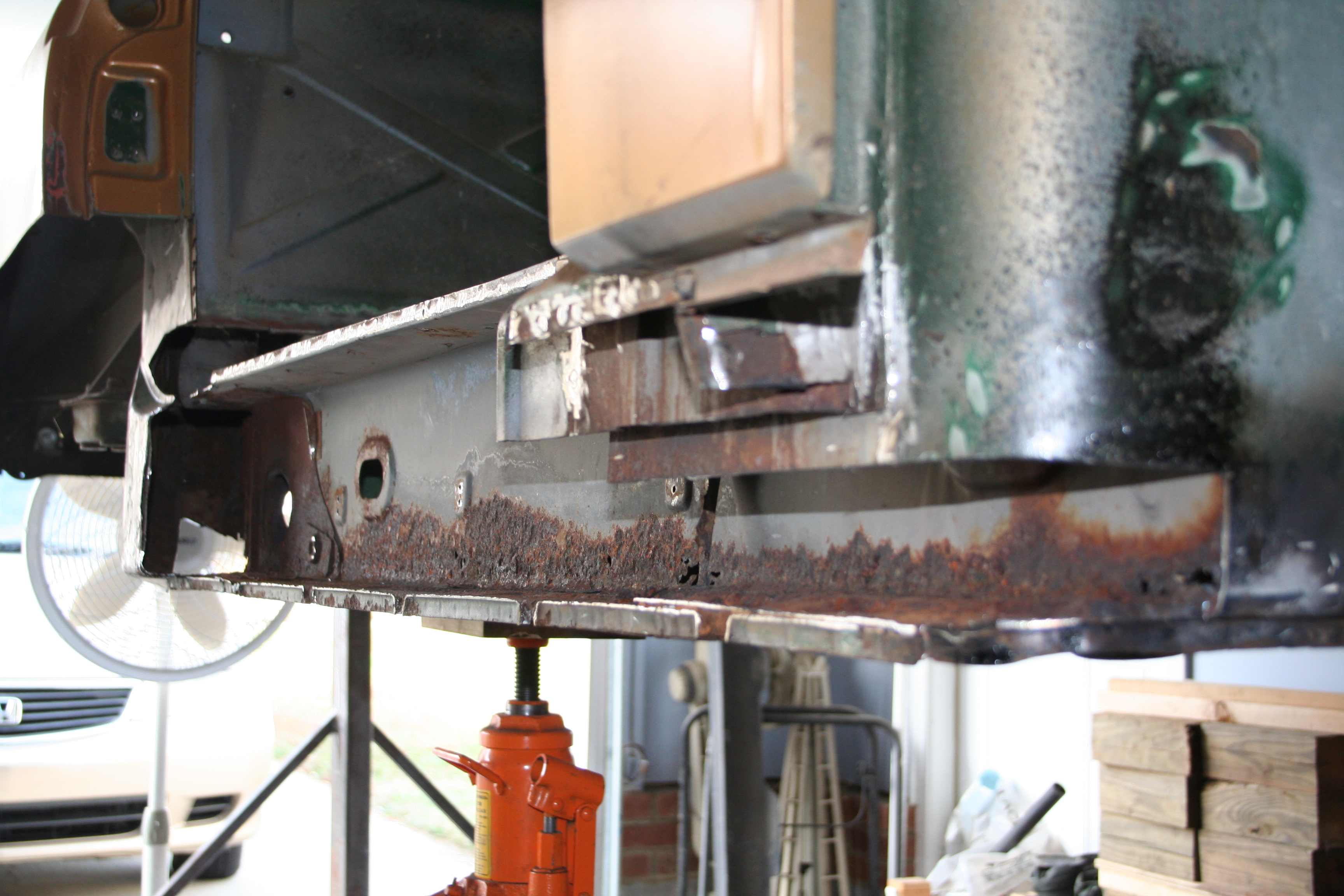
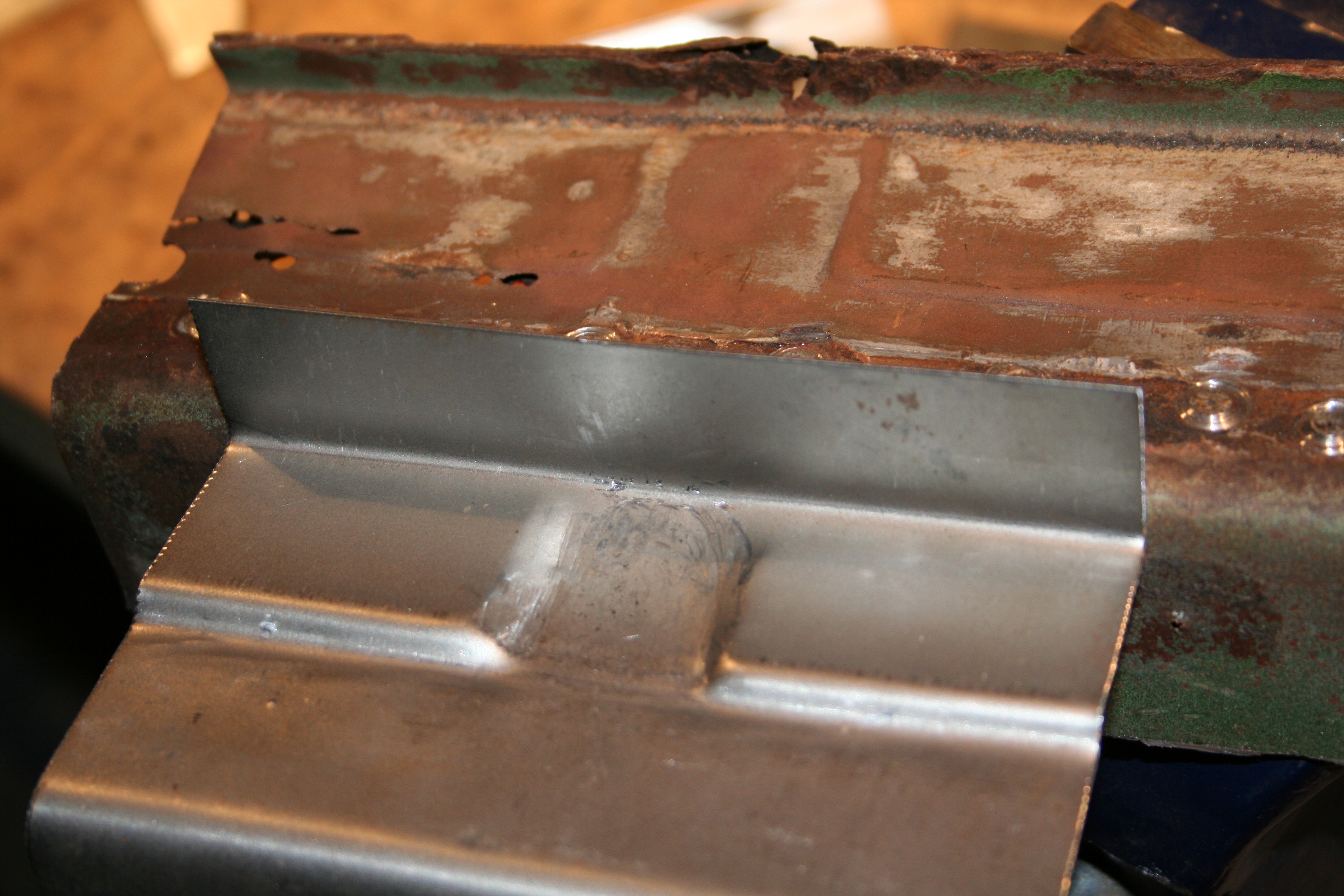
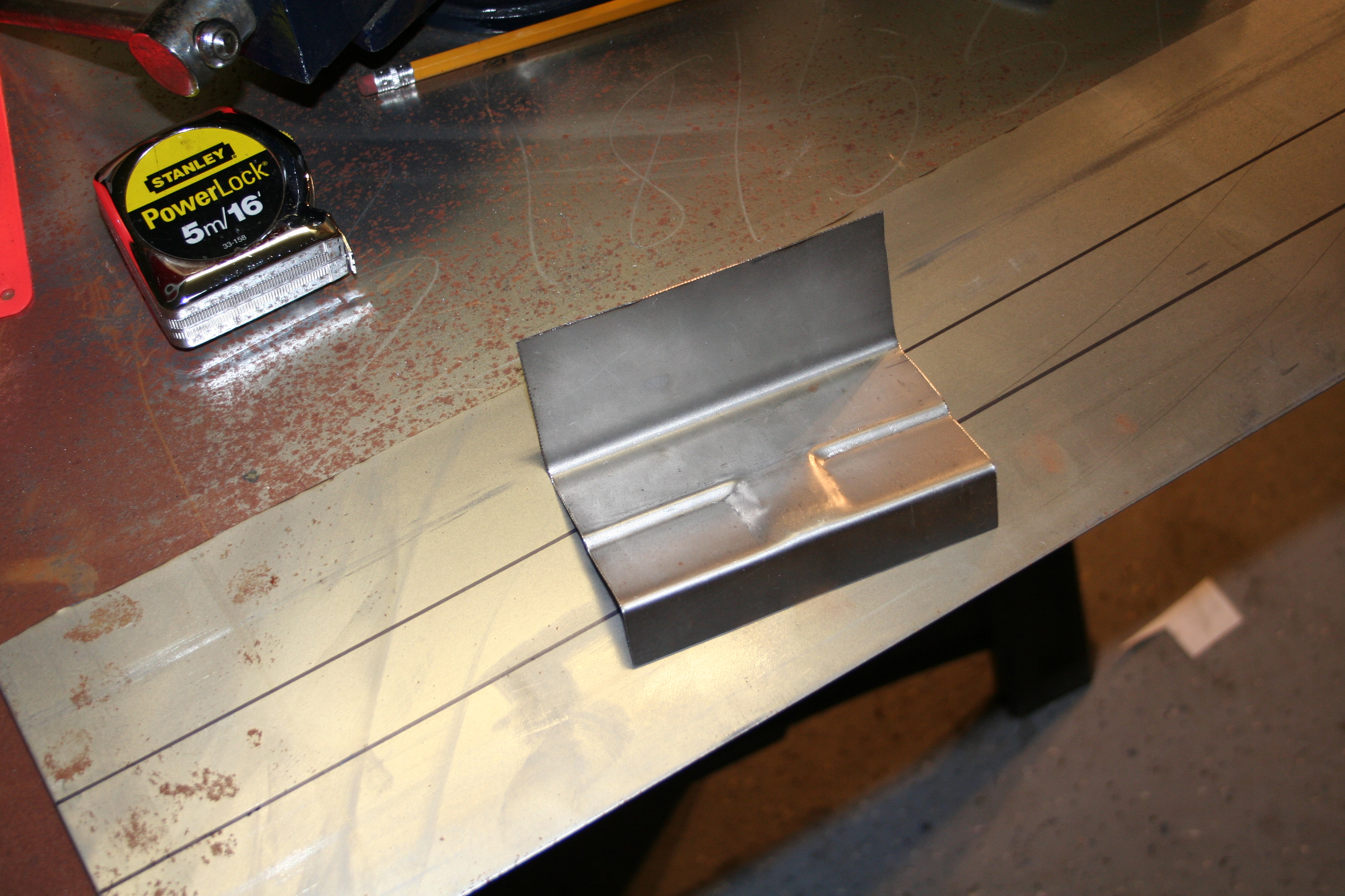
Here you can see that the next step is the section that is part of the front fender well. It is also behind the outer longitudinal.
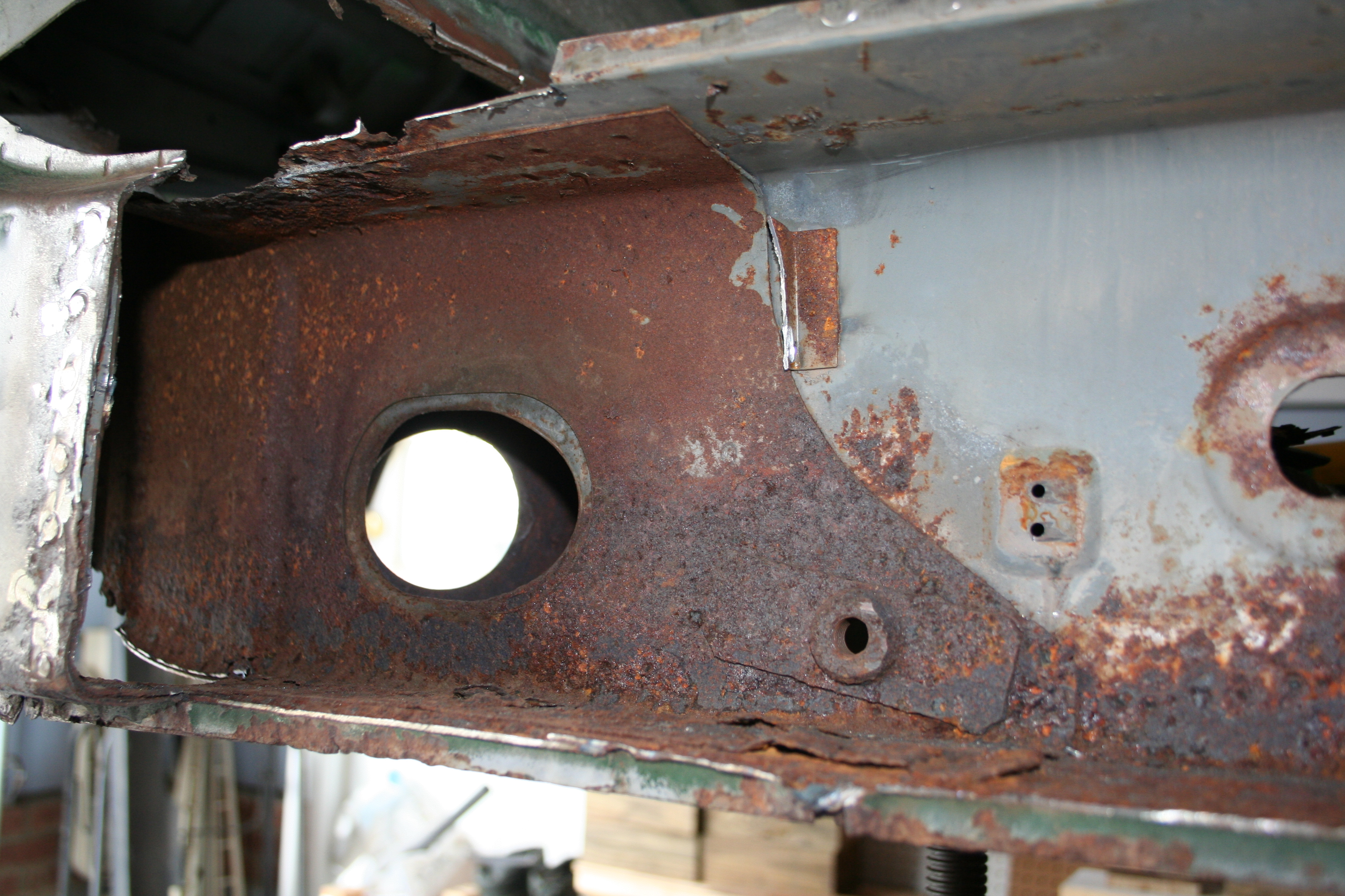
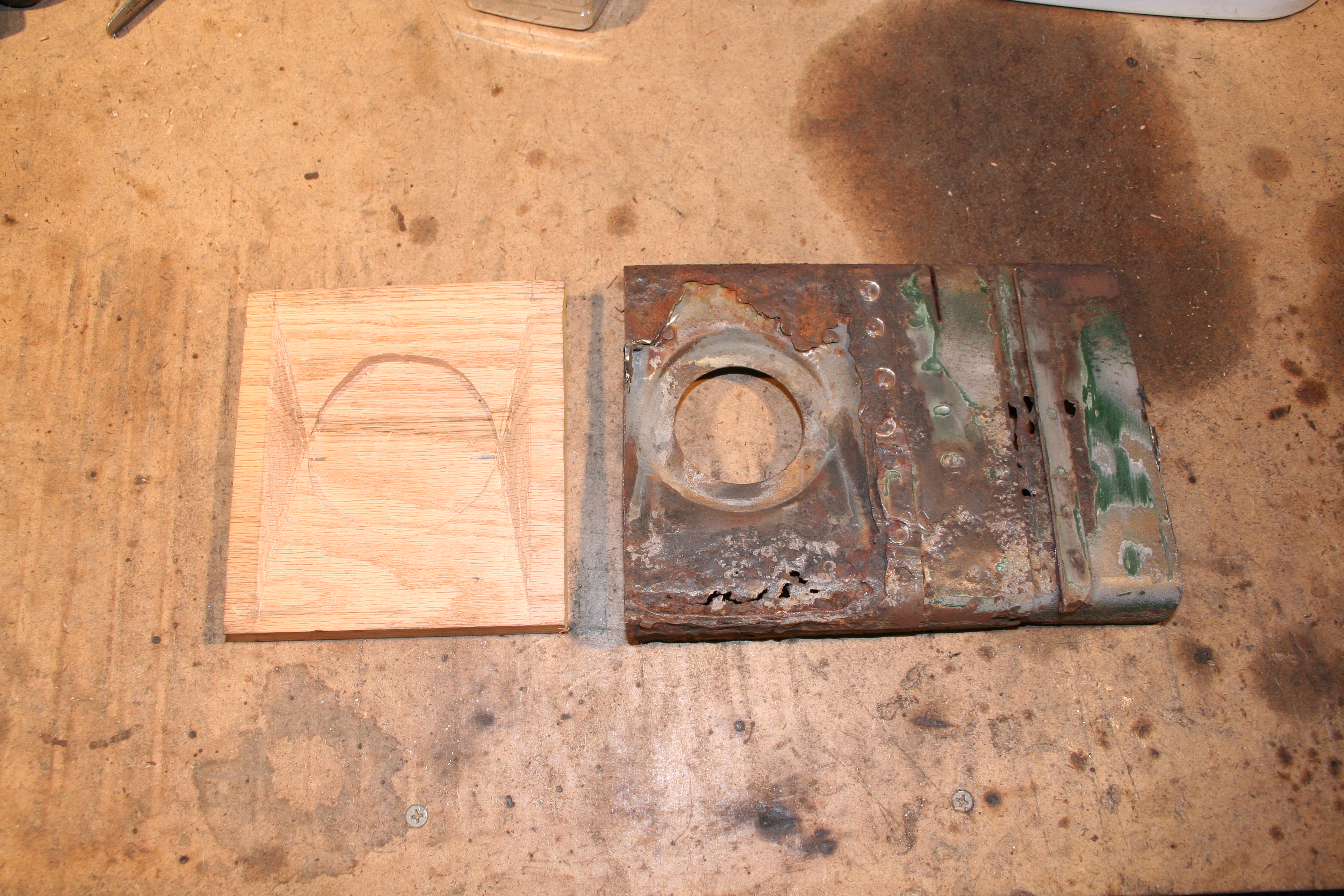
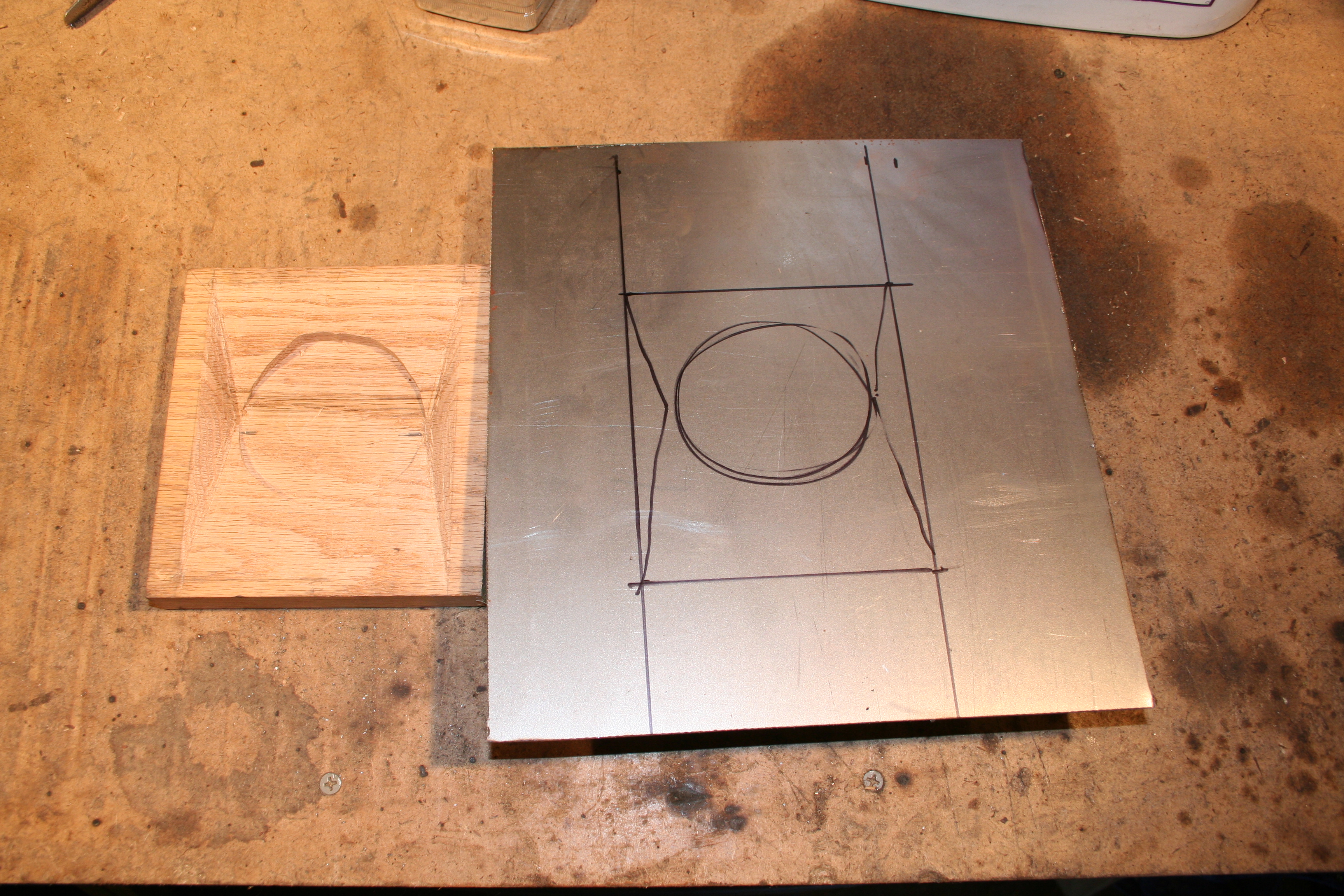
Here is the part I fabricated. I just need to drill some holes in the bottom for some rosette "spot welds" and then butt weld the top and edge. 9/21/2008I need to fabricate a replacement for the section of the longitudinal that is directly behind the jack receiver. This section is double walled with the inner wall actually having a circle cut out of the inner wall. It is also recessed a bit. I believe this is to allow for the jack receiver tube to extend father into the longitudinal. So my plan was to hammer form a replacement for this.
Here is the form that I created using a router and some chisels.
Here is my first piece with some rough guidlines.
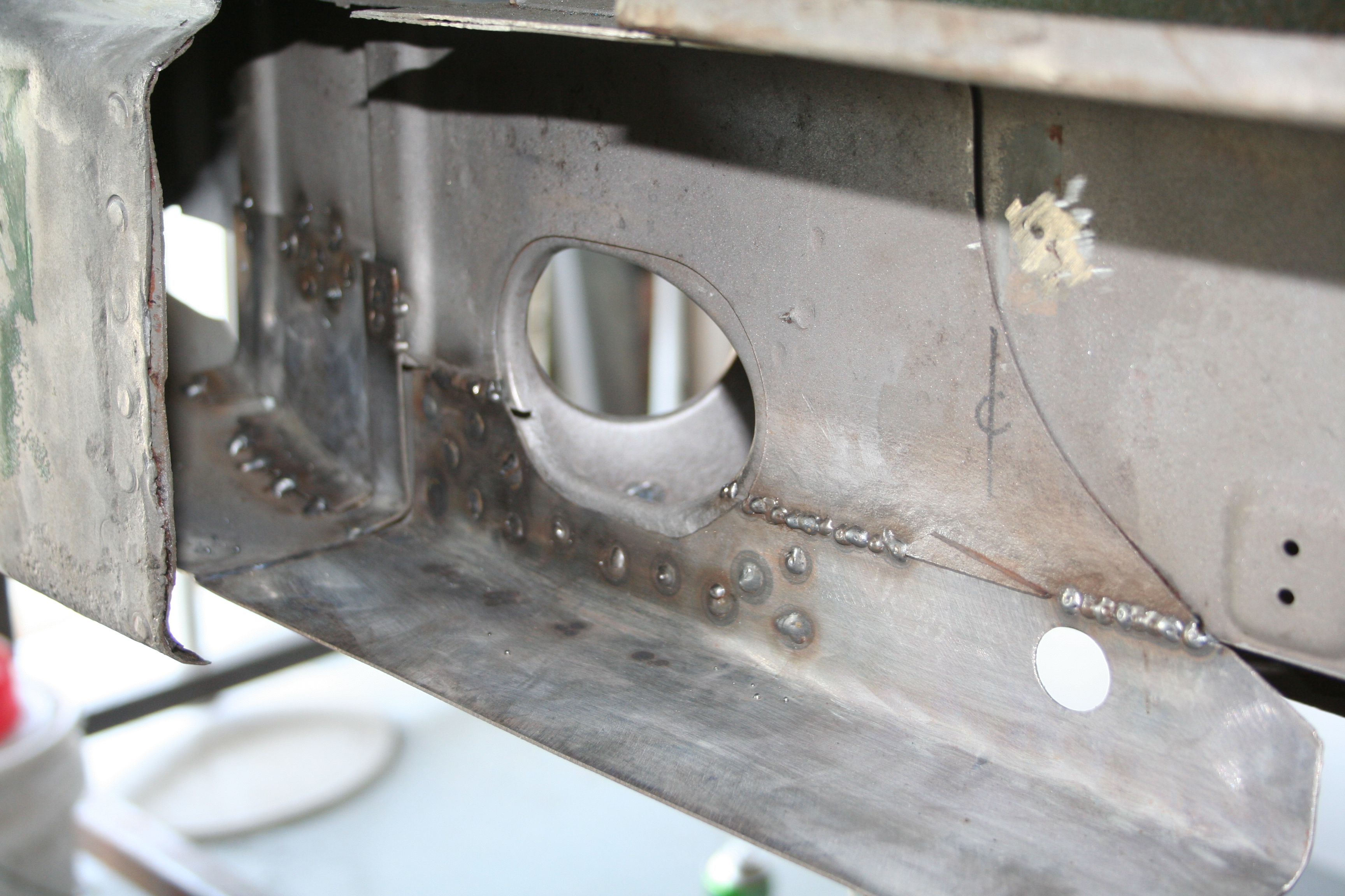
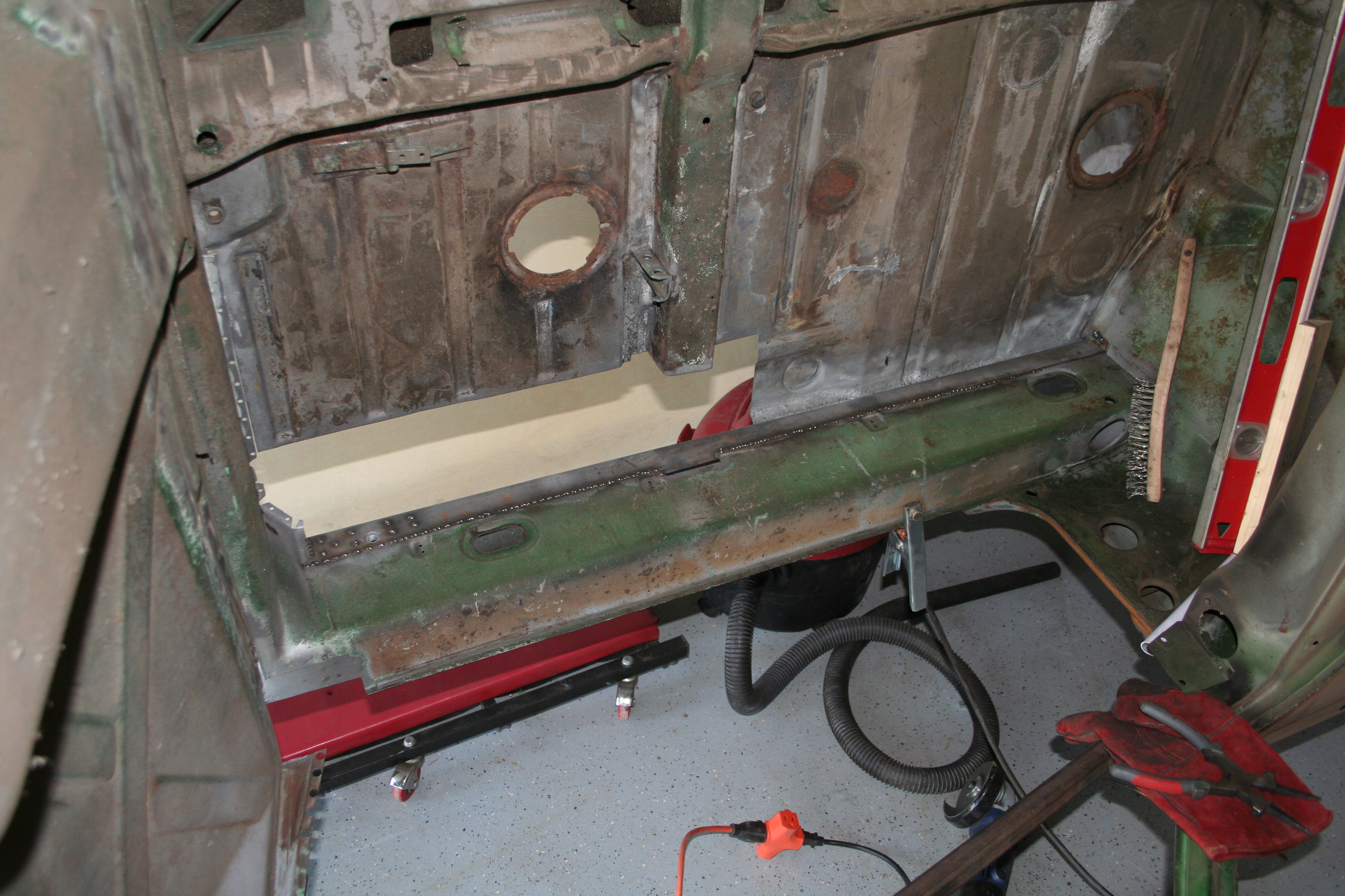
After hammering a bit, I am really not happy with how it is going. I know that I will be able to eventually get a rough shape, but it's not going to be up to the quality that I would like. So I am going to not use this form. My new strategy is to not replicate the hole in the inner reinforcement or the recess. But rather this is going to be smooth. The result is that the receiver tube is going to be a bit shorter than normal. But I think that is going to just have to be OK. 10/5/2008I am getting ready to weld in the replacement floor section and that is going to cover up the hollow bulkhead behind the seats. So I needed to go ahead and paint that with POR-15. The metal had already been media blasted and treated with Metal Ready, so I just painted the POR-15 on. This is the first time I have used POR-15. First that it has a really strong odor so you need to use it in a well ventilated space. Second it seems to go on well, but then run quite a bit. I had a lot of runs and drips to deal with. But overall, I am impressed with it.
Inside of the bulkhead. This is an area you usually never will see see in a 914.
While I was using one of the small POR-15 cans and theoretically they can be resealed, I went ahead and painted inside the longitudinal in an attempt to use up the paint in case it doesn't re-seal well. I will need to grind down some to weld in the brackets for the heater tubes as well as when I weld on the outer longitudinal.
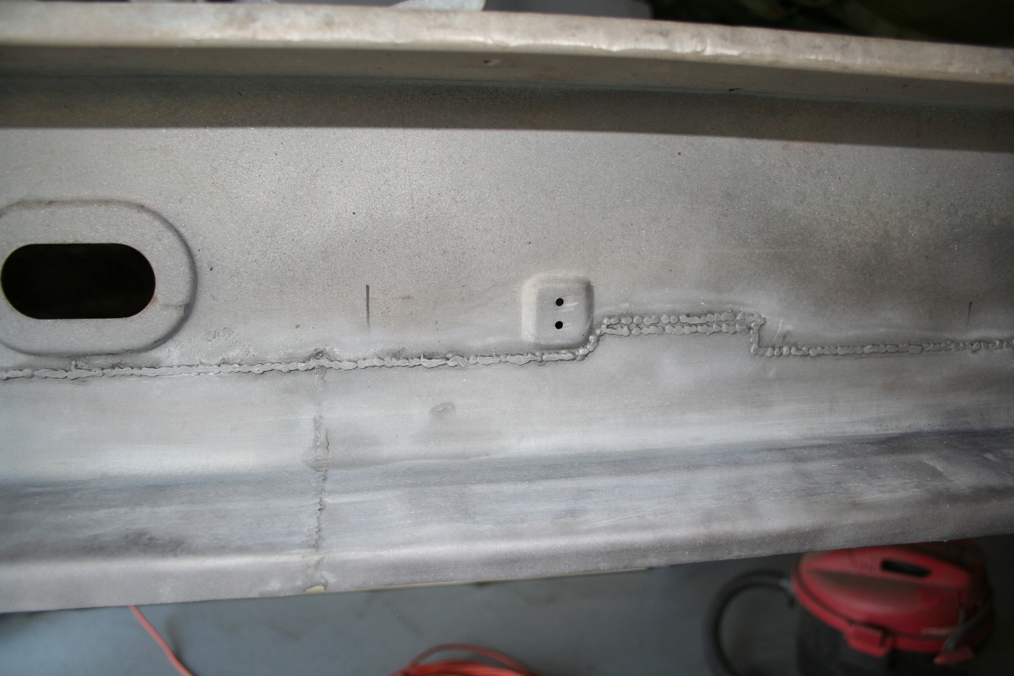
More of the same. 11/1/2008I had fabricated this section weeks ago and finally welded it in today. I will do some additional trimming of the length on the bottom when the put the outer longitudinal on.
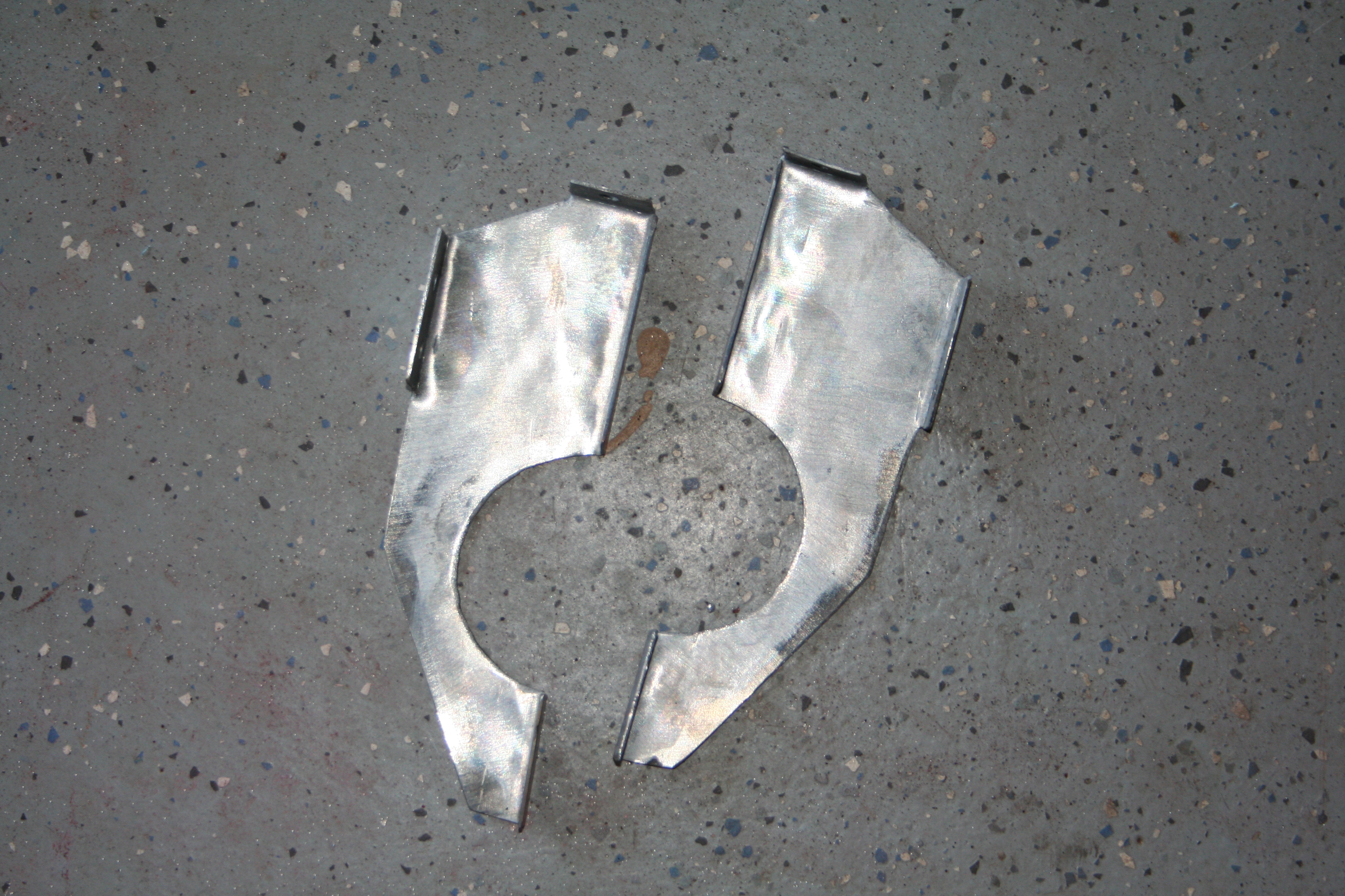
11/23/2008Now I need to work on putting the metal heater tubes back in. First I need to fabricate replacement brackets. I created a template based upon the remnants of the original rusted brackets. The same template works for both the front and rear bracket. However both have the "tabs" folded in a different direction.
Paper template plus two brackets cut out.
With tabs bent
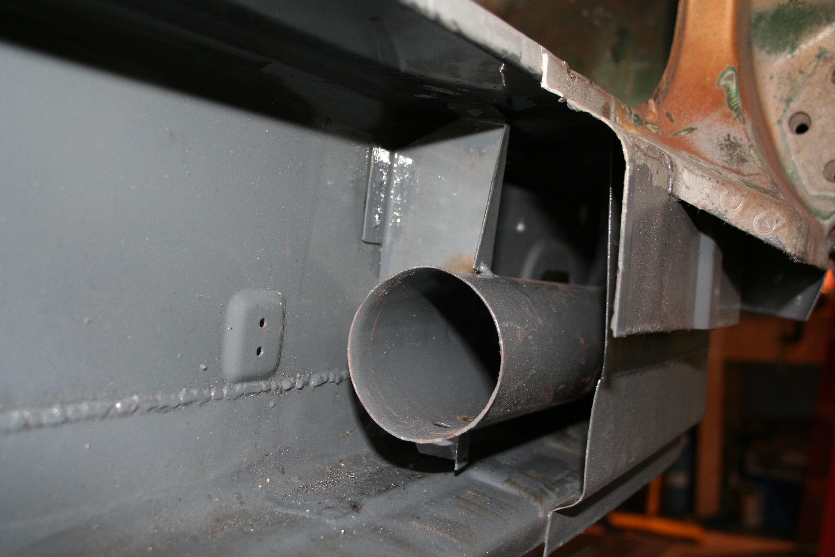
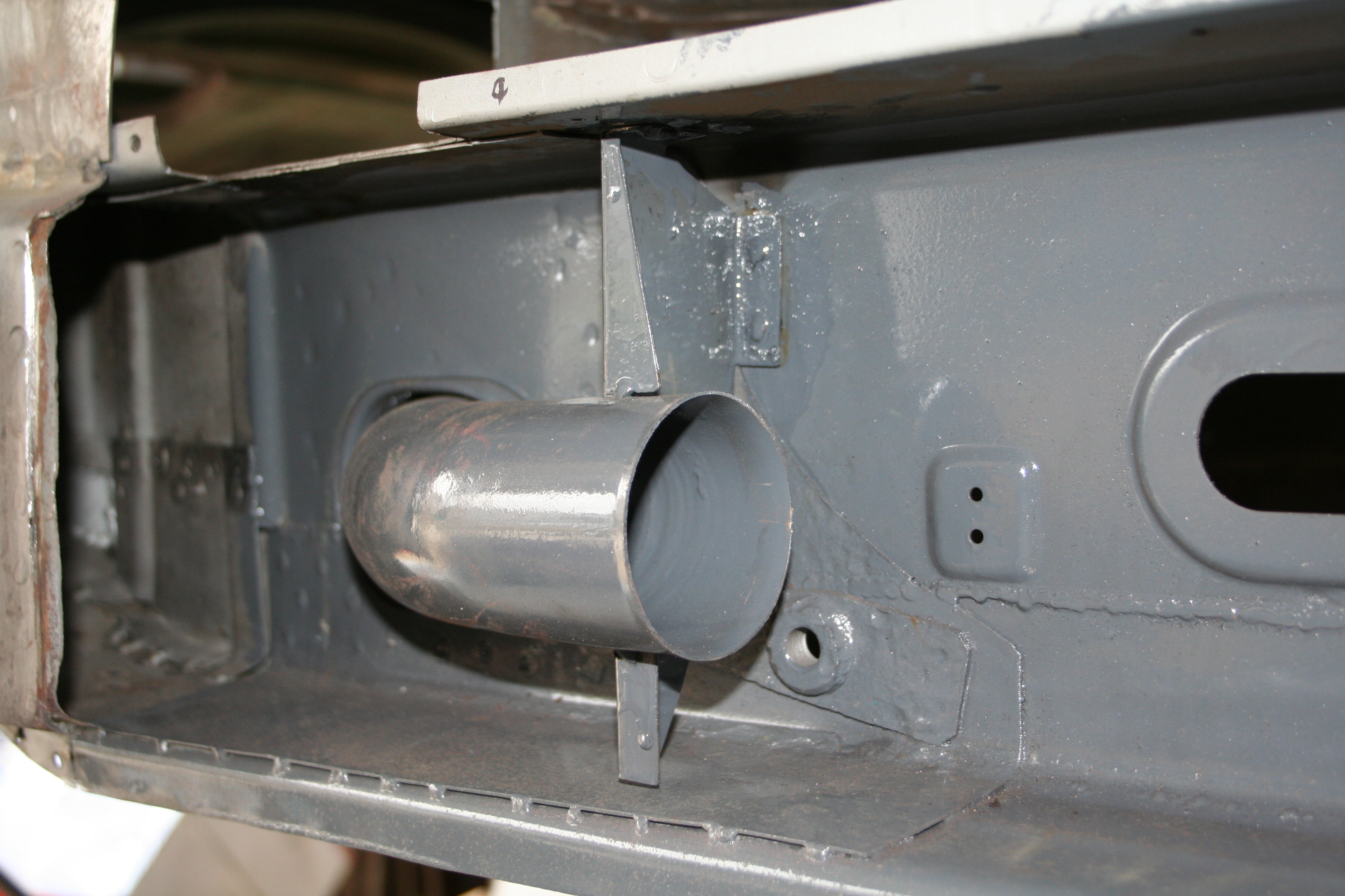
1/11/2009I can't remember what day I did this on, but it was sometime in December. I welded in the brackets and the metal heater tubes. Everything has been painted in POR-15. It all went together pretty well. I have test fitted the actual heater tube and it fits fine. I have the three "U clips" that hold the tube in place ready to go. Those are riveted into place. However before I put them on, I want to finish some welding on the interior side of the longitudinals. Those welds will burn through some of the POR-15 and I want to touch that up before I close this section up. If you look closely you see red powder coating dust on stuff from when I was powder coating the front struts.
2/13/2009Fabricated and welded in this small section. I replicated the small "half moon" indent in this section.
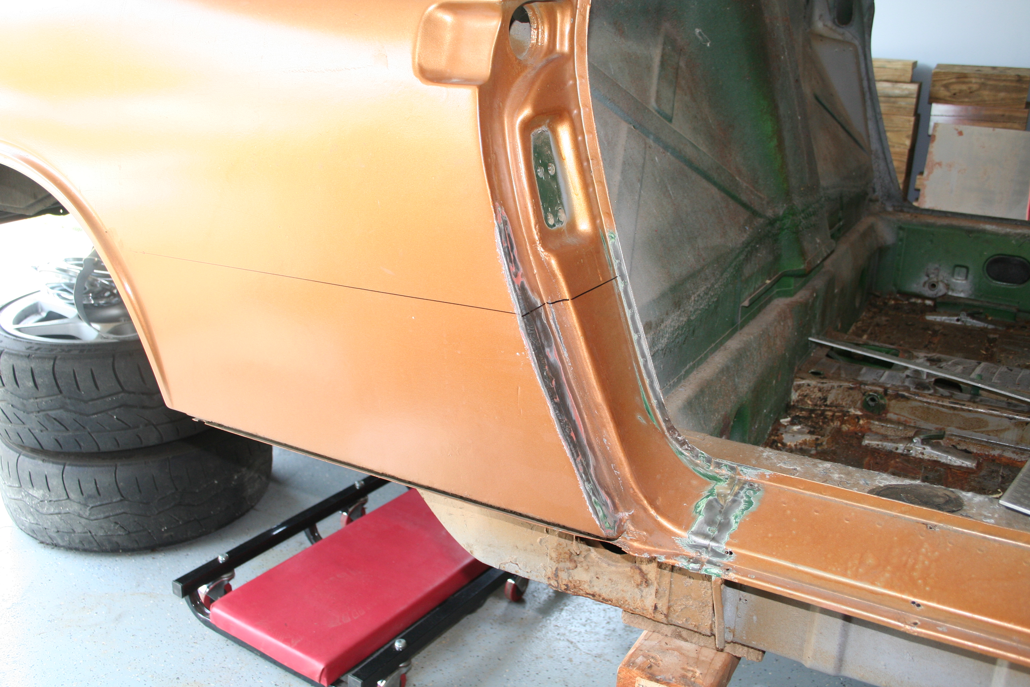
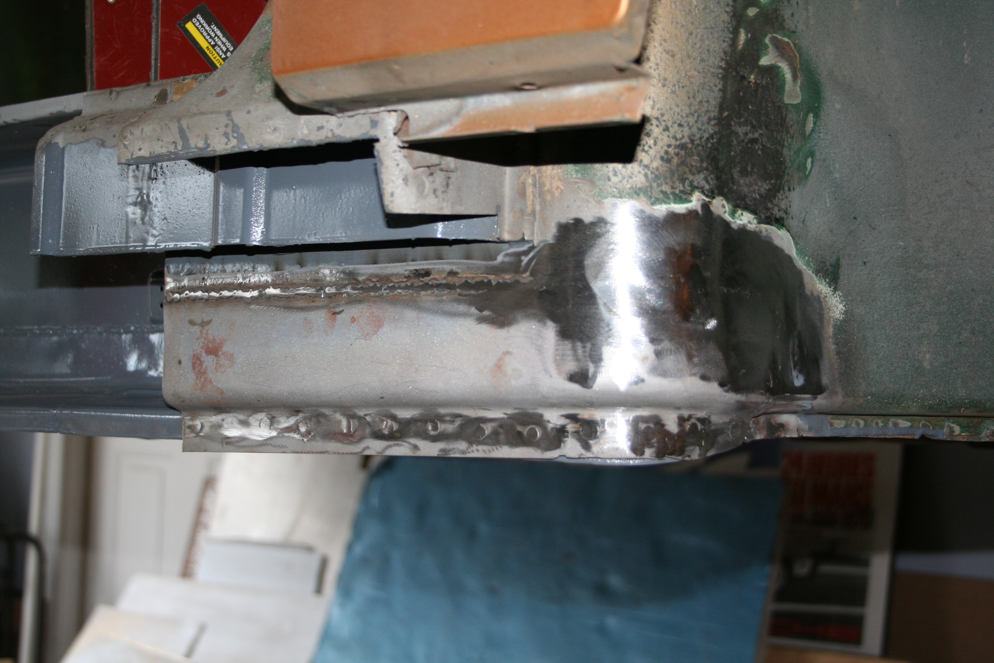
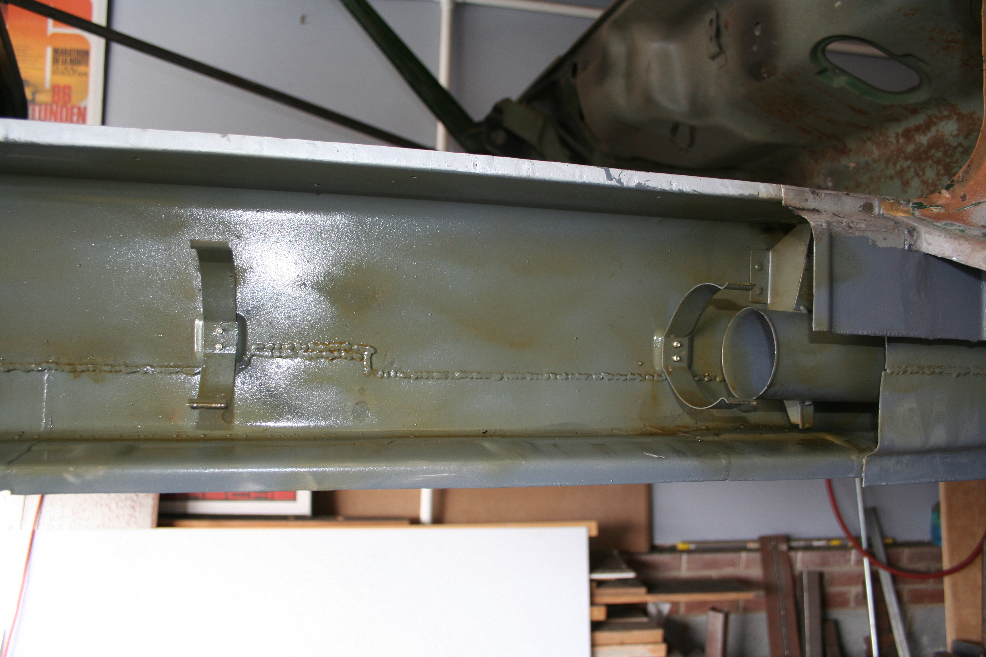
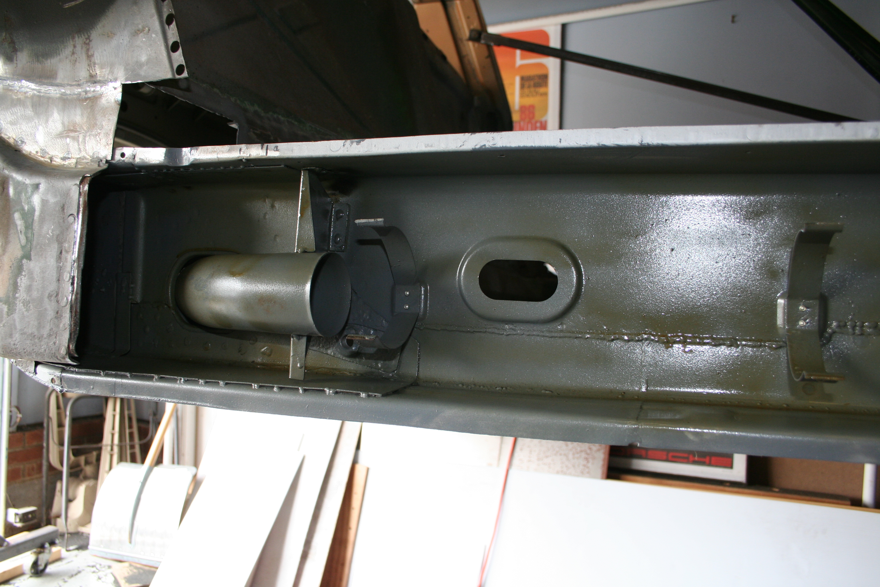
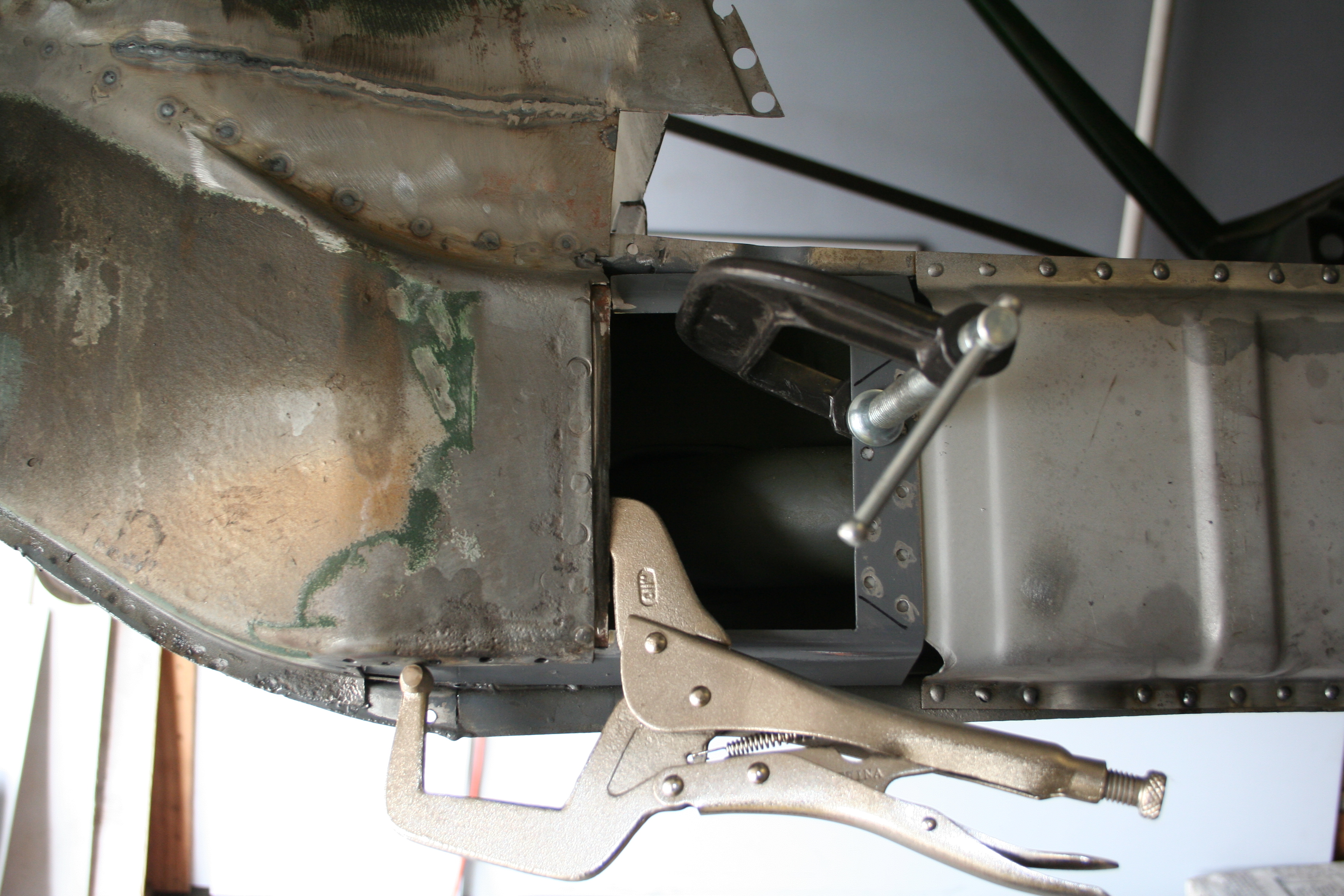
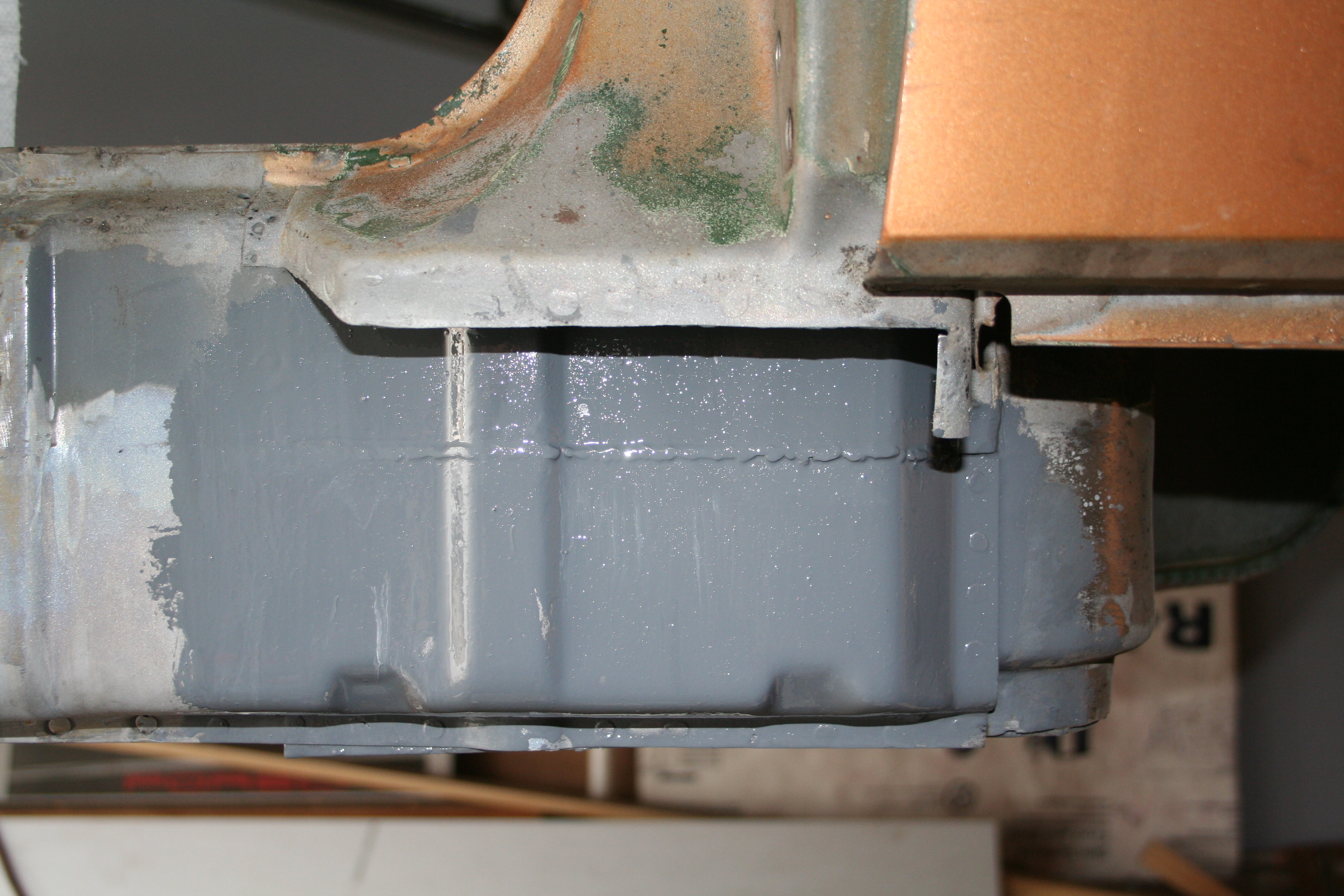
2/15/2009Ok, I am finally ready to weld on the outer clam shell onto the longitudinal. I had riveted in the three clamps for the heater tube and painted the inside of the outer shell a few days ago. Then today, I sprayed the interior with my CRC anti corrosion spray (wax). That is what the yellow/green stuff is. Then I put back in the heater tube in place and then welded the outer clam shell into place. I double checked the gap at the top of the car (no change due to the braces that are holding the upper car in place. I then worked on making sure that the clam shell was positioned correctly by using some long straight edges. Clamped all of this in place with many vice grips and then welded it up.
Spray on wax
Tube in place. It fits pretty snug and it was rotated back into the exact position as it was when I removed it.
Seam weld started
Seam weld finished, but not ground down yet.
Rosette "spot" welds are looking good.
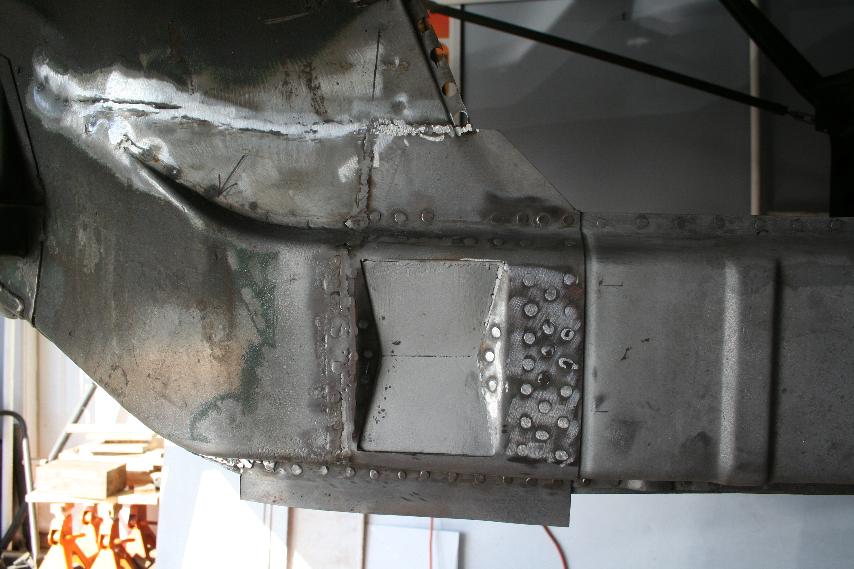
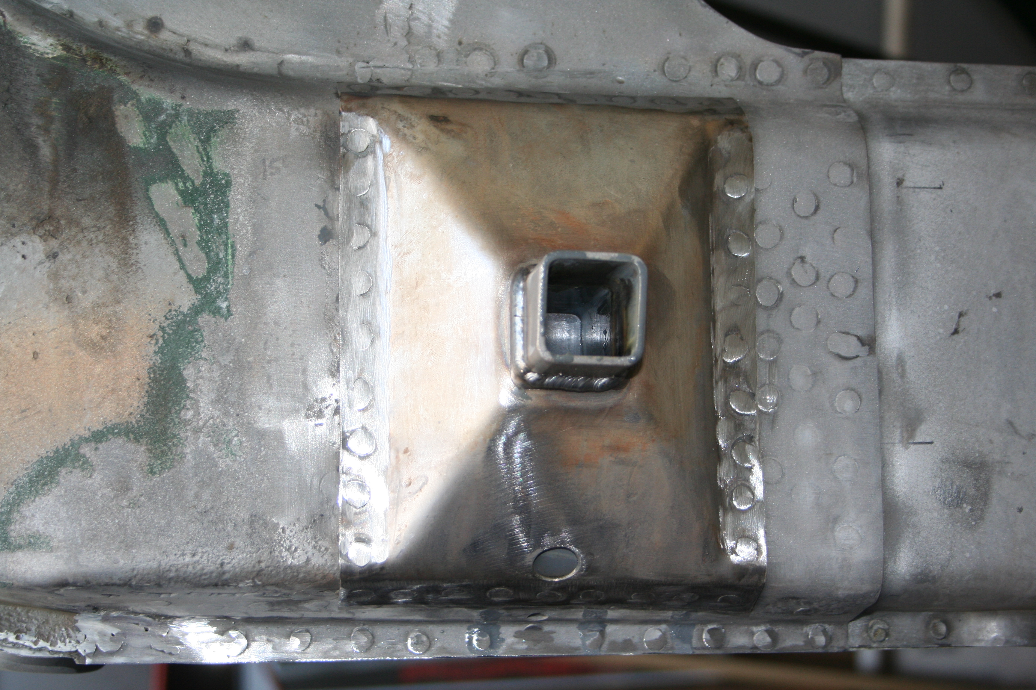
I was very excited to get this done. It went very quickly. 2/26/2009Now it's time to move onto the area right under the jack receiver pyramid. This is a double walled section with a 13mm recess. I believe that with the factory stamping, there is a small flat section where the receiver tube is welded to in this recess. It was going to be a pain in the ass to replicate that flat spot, but much easier to make it more of a reverse pyramid. This will require me to create a slight "V" shape to the tube, but this will only maybe be about 3mm and will only be slightly different from the factory stamping. But the first step is to fabricate and get in place the basic inner section of the double wall. Additionally there needs to be a notch in this to make room for the nut that is welded onto the final outer wall. The nut is needed because this is what holds the bolt at the bottom for the rocker panel. It is right below the receiver tube.
Clamped into place and ready to weld.
Once that is welded into place, then I can start the inner wall of the recess. This section has the 13mm recess.
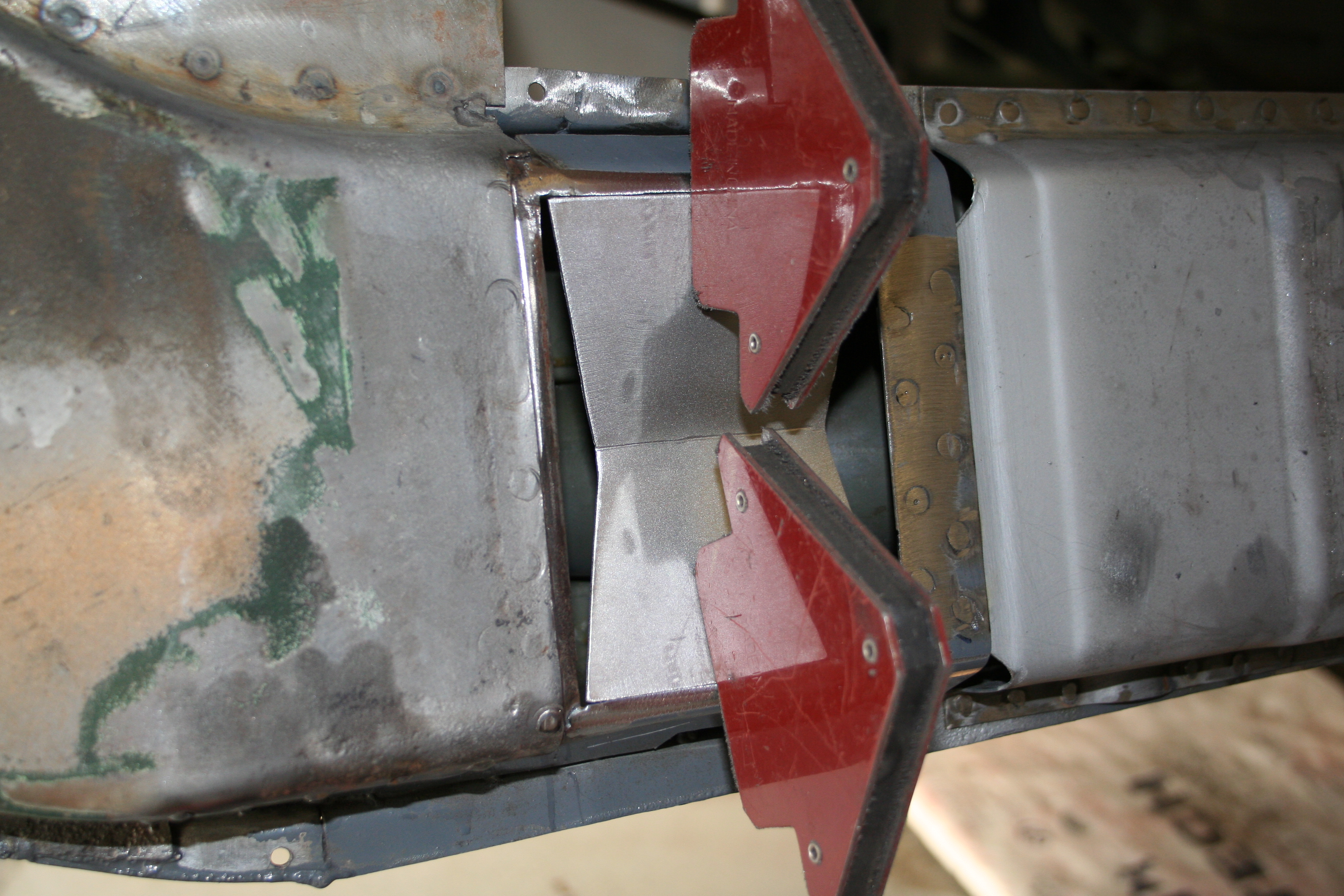
Mostly welded in place. I need to two smaller triangles to complete the reverse pyramid. Even then, this is just the inner wall. 3/15/2009I finished up the first/inner layer of the double wall and now am working on the second/outer layer. I actually had started forming this piece awhile back, but was unhappy with how it was turning out. So this is the second attempt. Here you can see the rough shape with two bends in it.
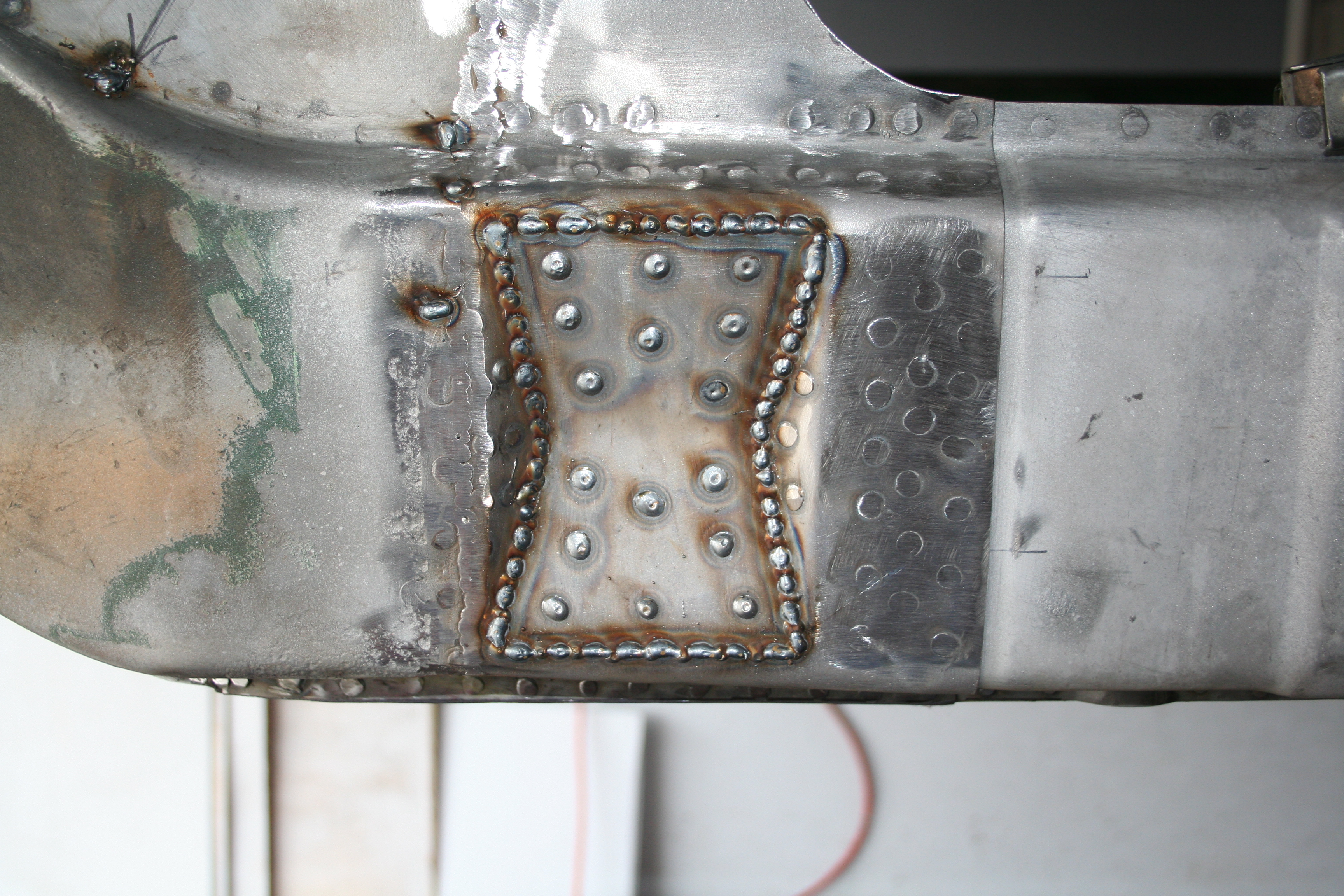
Working my way from the bottom to the top. Using a combination of metal brake and pounding over curved forms. 3/22/2009Final forming of outer layer, welding into place and first steps of welding the jack receiver tube in place.
Here is the finished and media blasted inner layer.
Here is the finished outer layer, but prior to being welded into place. This is the inner surface that has been painted with weldable primer. Note the nut on the bottom. This is for the rocker panel. It has three nuts on the bottom of the longitudinal. The last is right under the jack receiver tube.
Plug welding from the inside out.
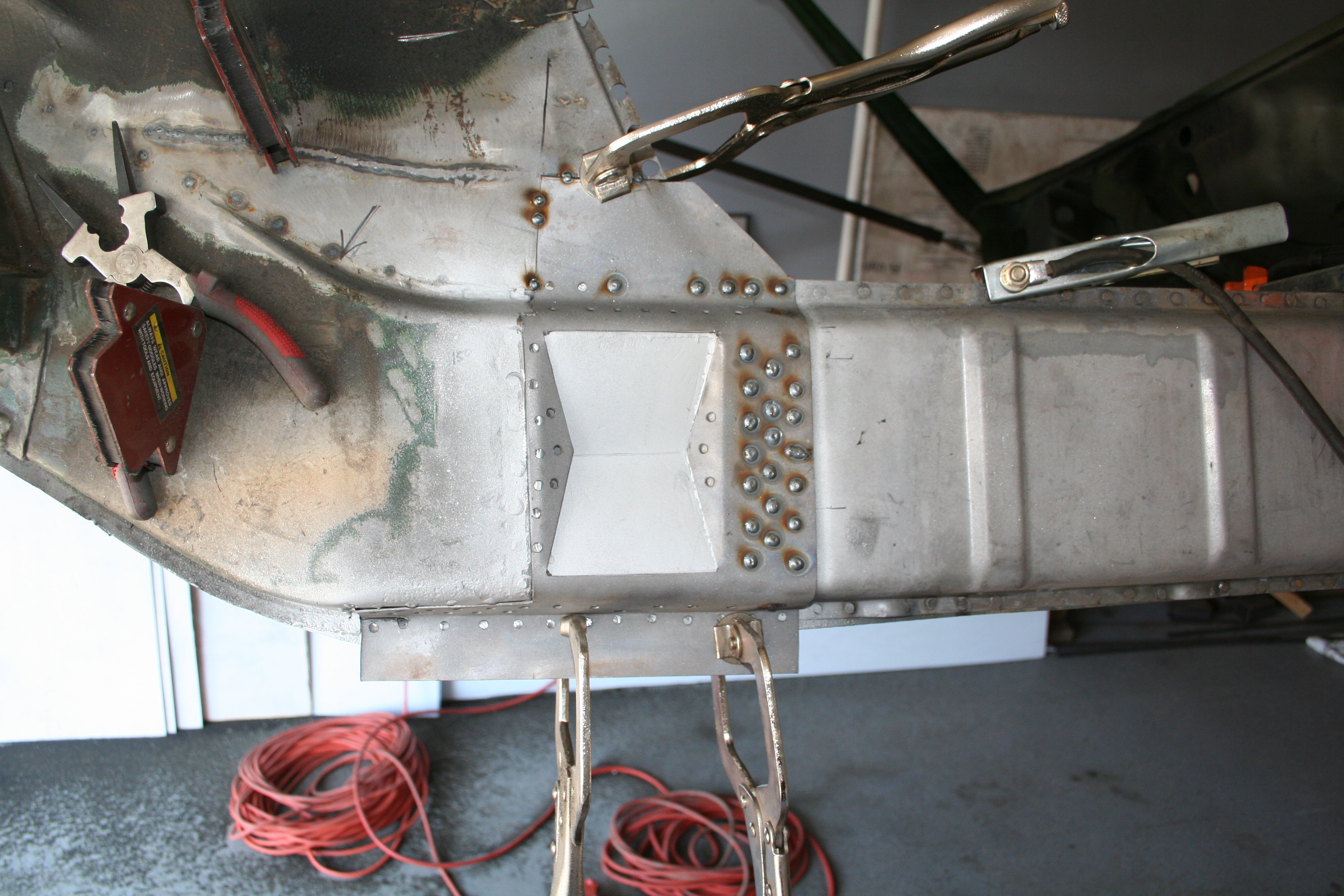
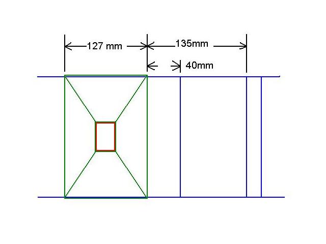
While welding in this general area, I decided to put in the triangular section that hosts the rear donut. I tried to measure the location of the good one on the driver side to get the correct position. The passenger side receiver tube and pyramid was totally gone. On the driver side the flange of the pyramid was still there. So I was able to measure it's exact location. The pyramid measured 127mm wide. It's edge was 40mm away from the seam from the front and rear sections. It was also 135 mm away from the top edge of the raised section on the longitudinal. There are multiple raised sections and each are about 150 mm apart. I would not be surprised if it as to turn out that the receiver tube was +/- a few millimeters either way on different cars. There is some evidence that mine from the factory left to right were not identically placed.
Check out the work I did on the driver side receiver tube here. I worked on both driver and passenger side at the same time, but did the driver side work today.
Donut in place.
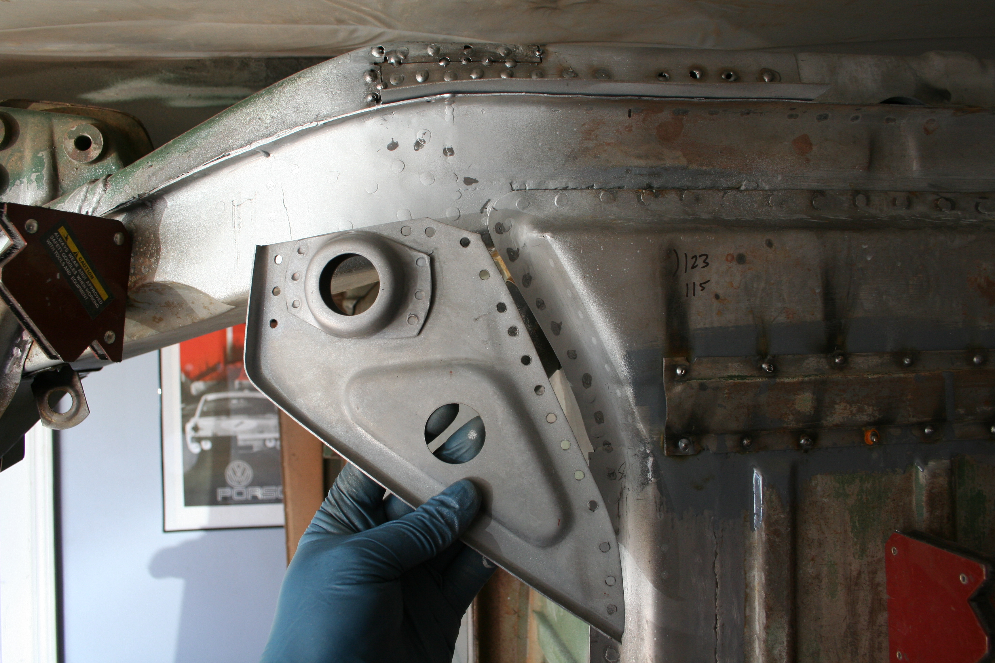
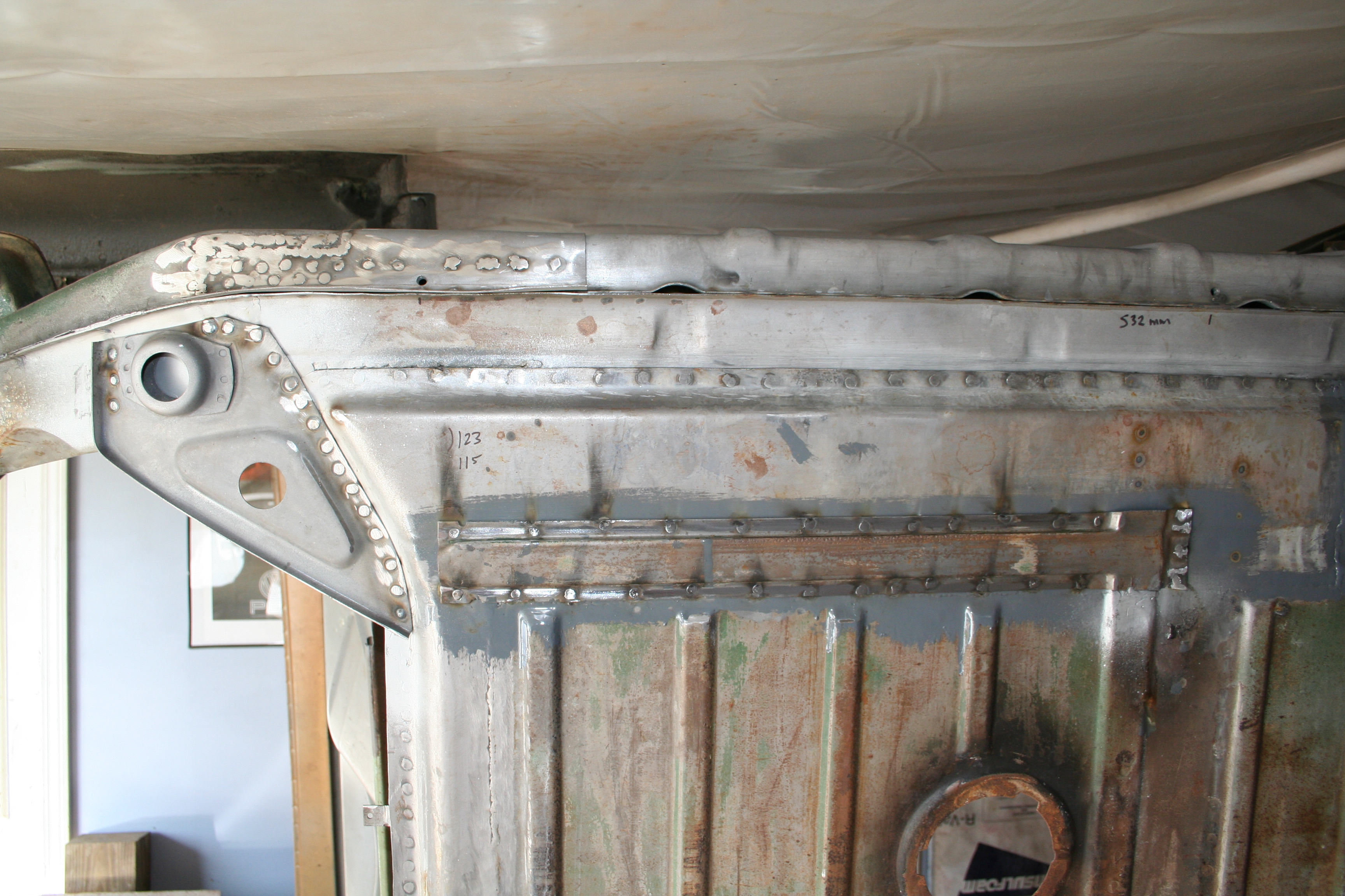
Passenger side with most of the outer layer in place. I still need to weld in the bowtie shaped piece. 3/27/2009Final work on the inner layer and welding the jack receiver tube into place.
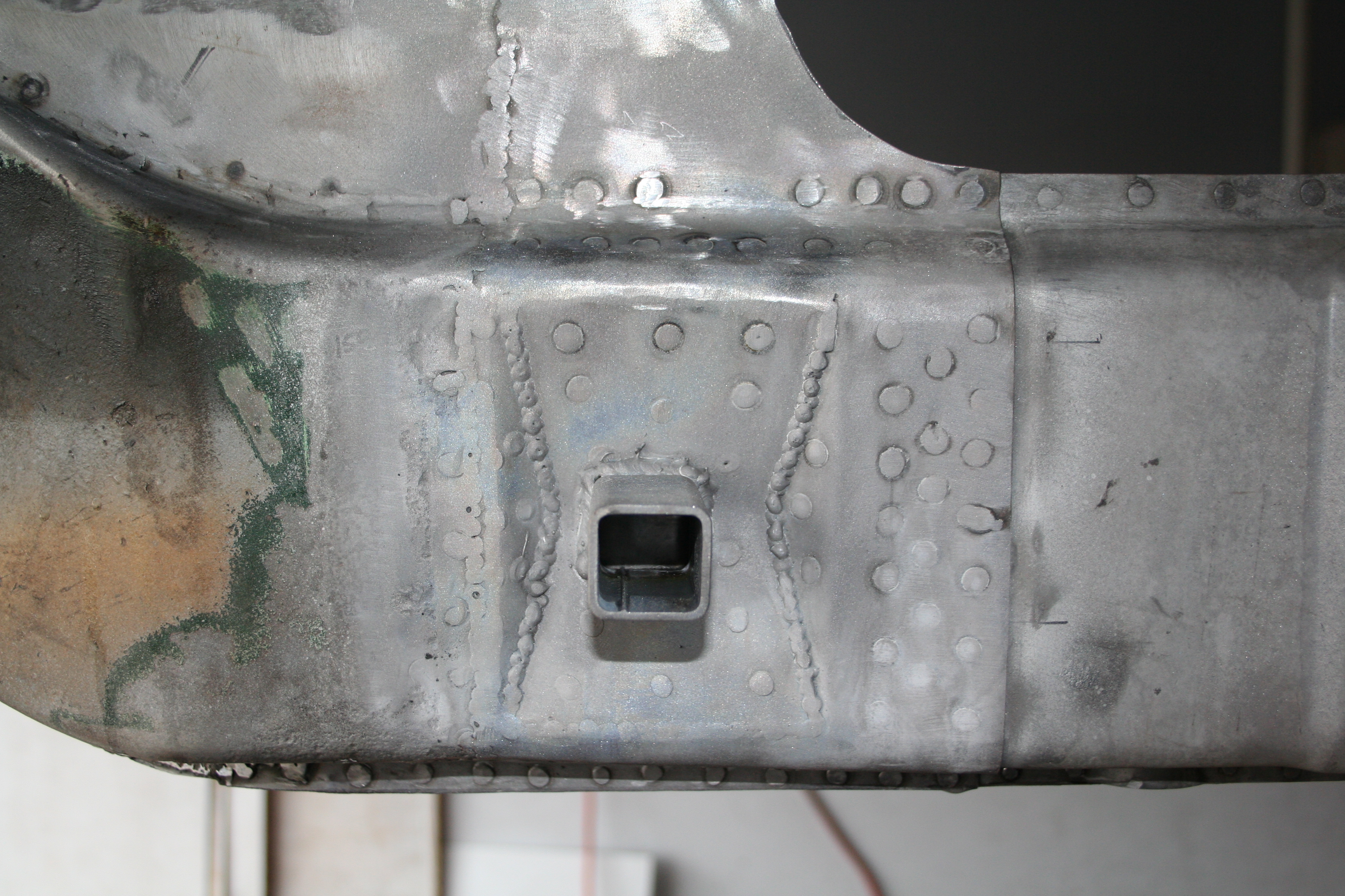
Final outside layer welded into place.
Welds grinded down, tube welded into place, media blasted and treated with Metal ready. Nice white metal.
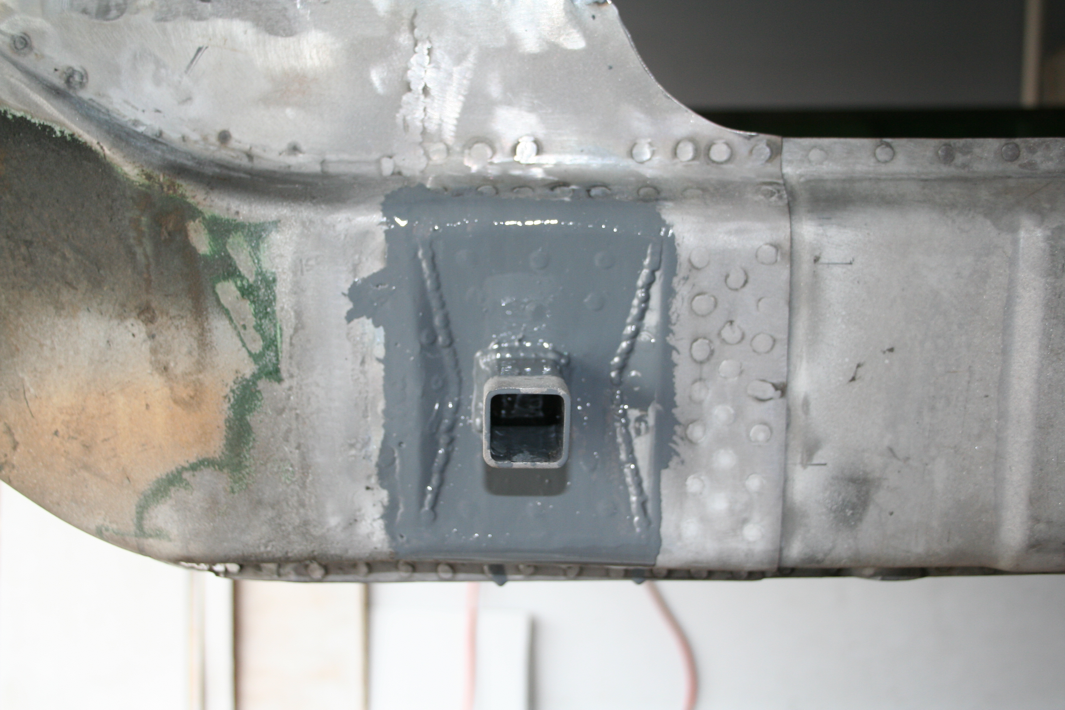
POR-15 on the inside. After this dries, I will weld the pyramid in place on both driver and passenger side.
While I had the POR-15 out, I painted the inside of this cavity on the front. After I finish the jack receiver tube and pyramid, I will fabricate the cover for this cavity. 4/12/2009More work on the jack point...
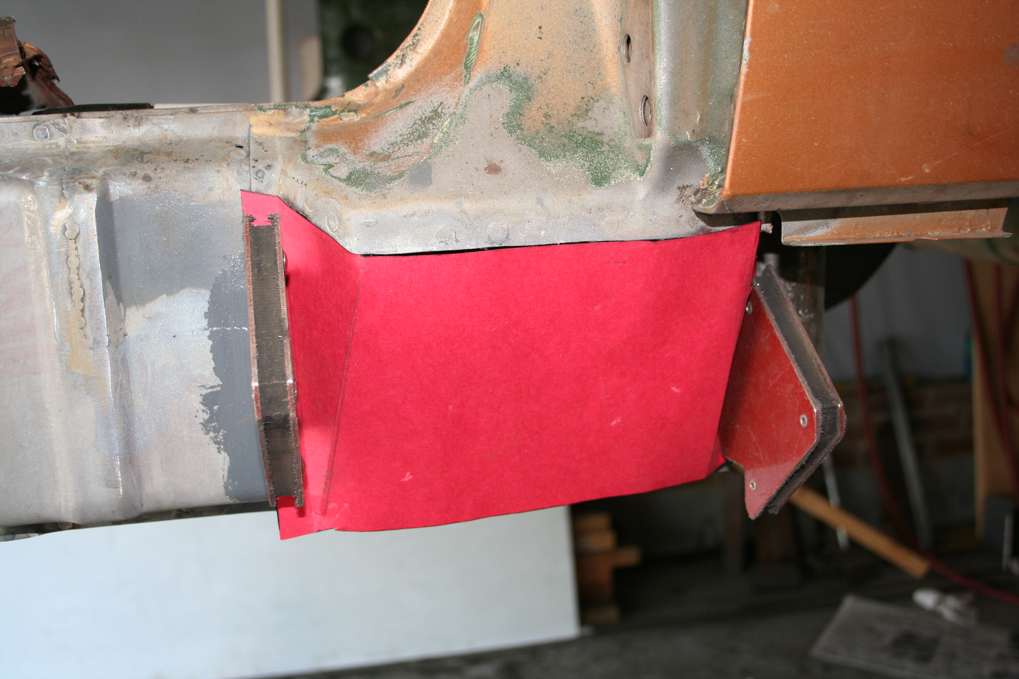
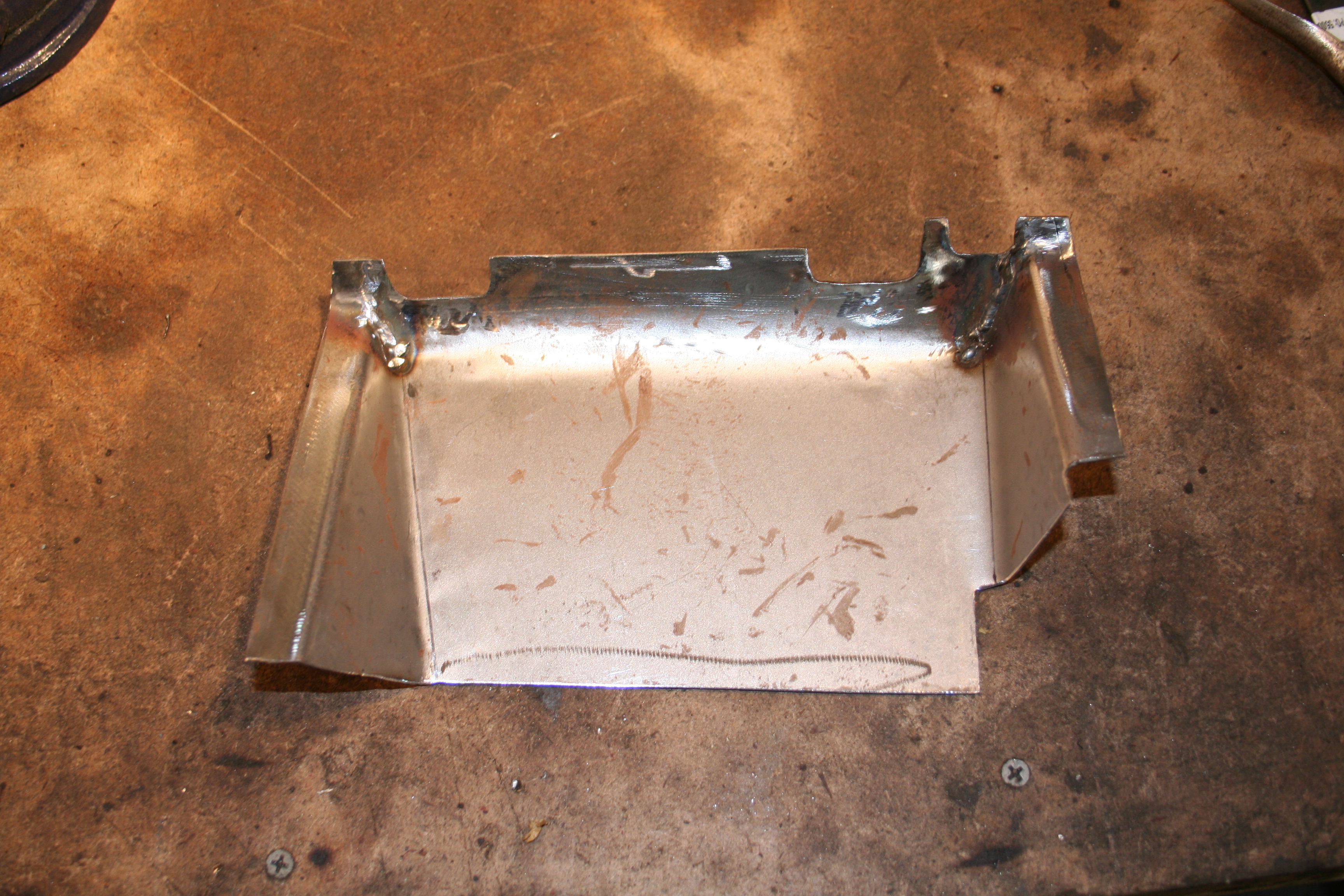
Then weld in the pyramid. Prior to welding I removed the POR-15 in the small area in which I would be doing the rosette welds. You will notice that my pyramid has a non-stock hole in it. I basically added a drain hole and also made it large enough that if debris gathers, I can dig it out. Many people do not replace a rusted jack point and pyramid. In my opinion one of the reasons they rust is that this section is enclosed and can't properly drain. 4/26/2009Almost done with fabrication of parts for this part of the car, but I have one last major part to do. That is the boxed section below the door hinges.
Paper template.
Cut and bend. Note notches match original. 5/3/2009
Weld and grind
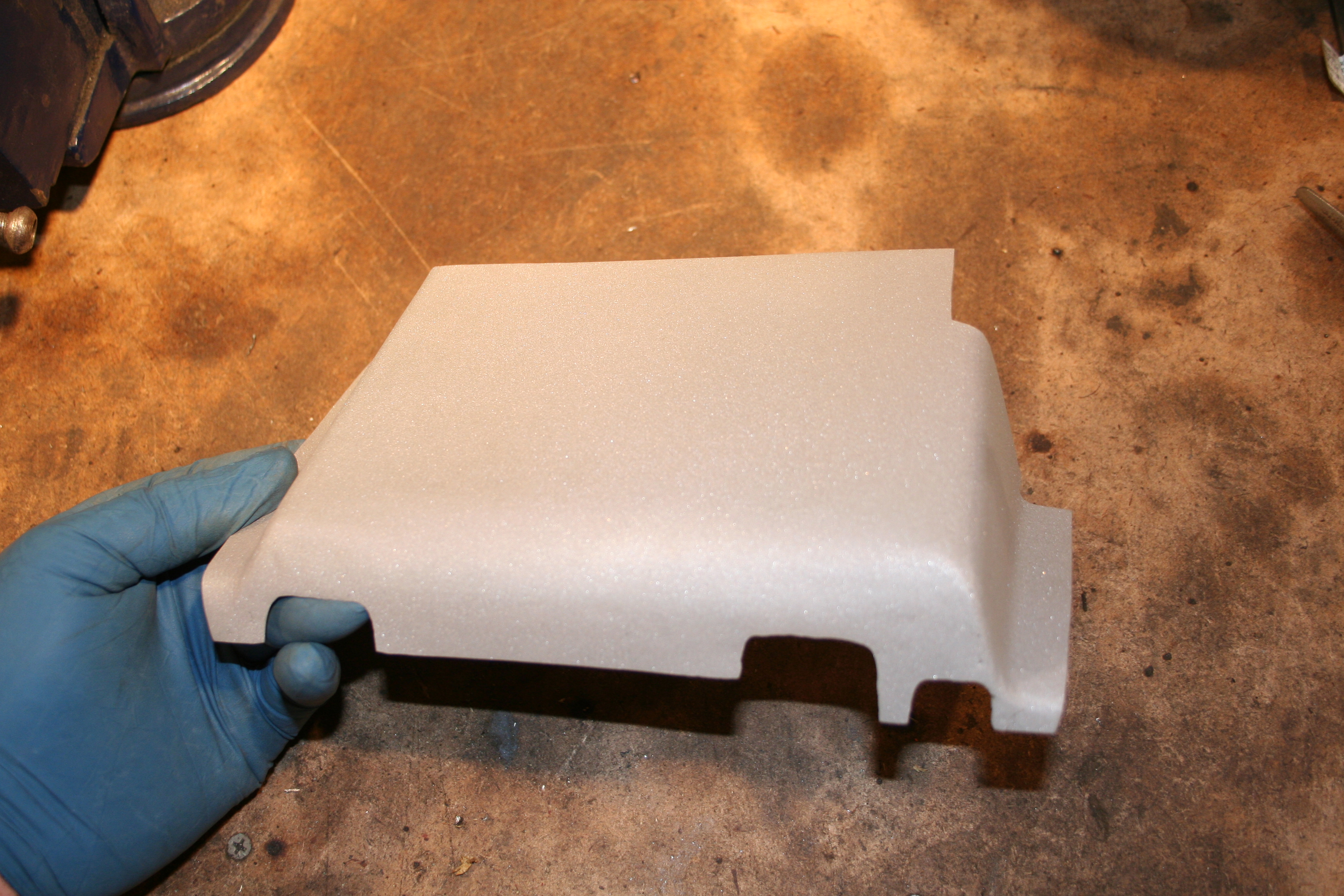
Interior has welds that don't need to be ground 100% flat.
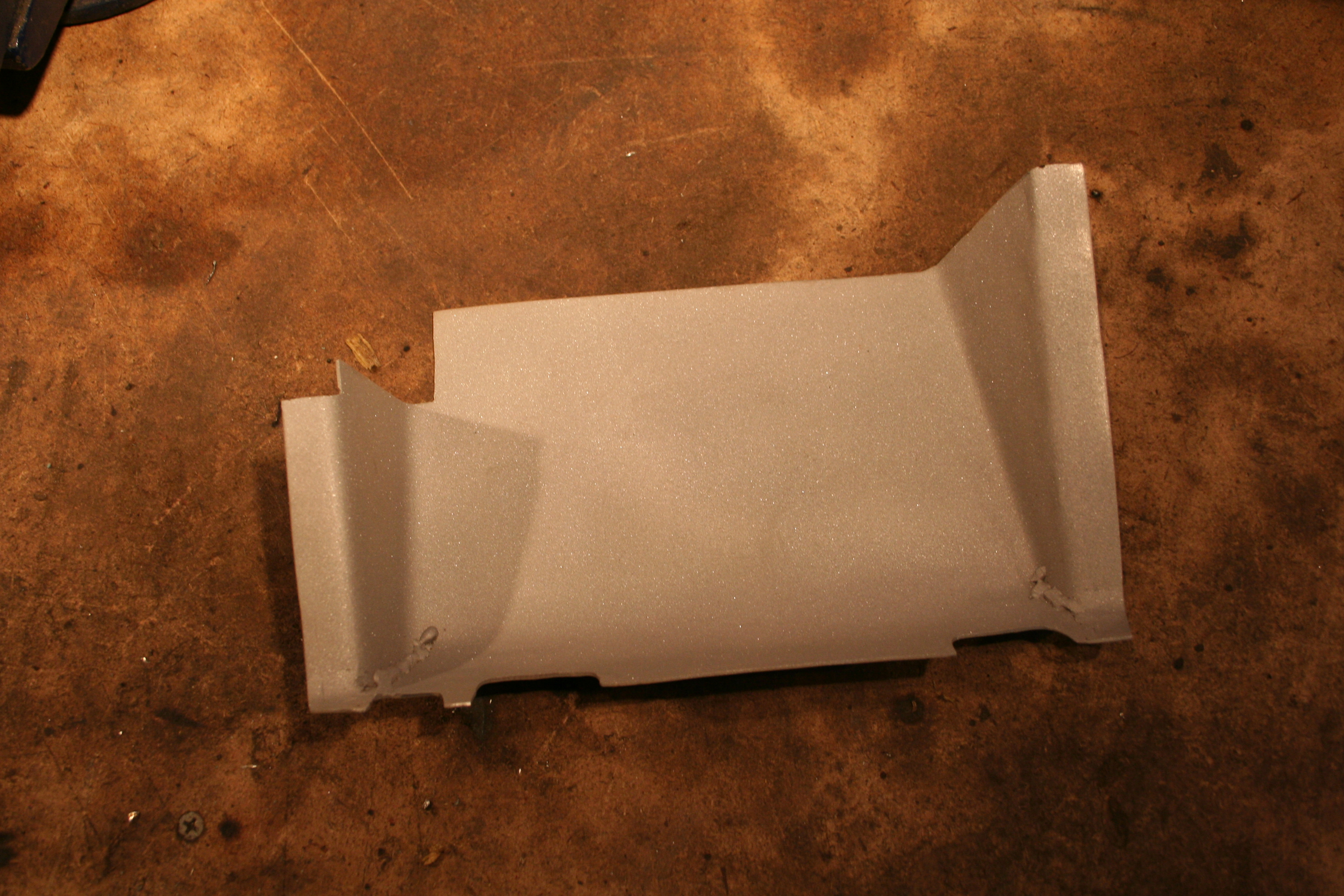
Media blast and treat with Ospho. It looks really nice at this point if I say so myself.
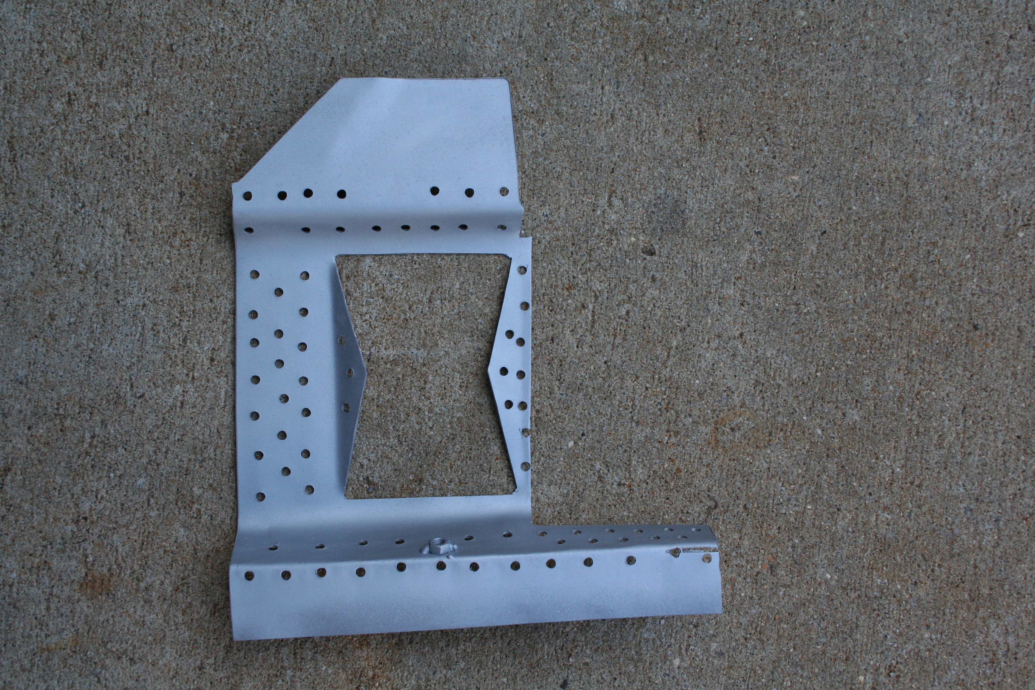
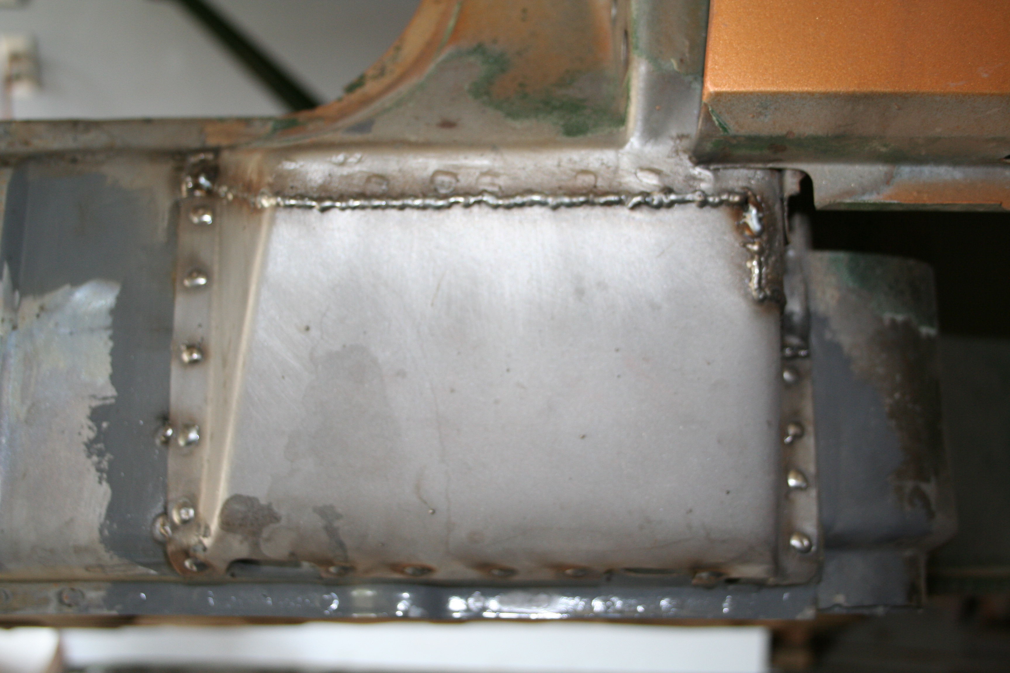
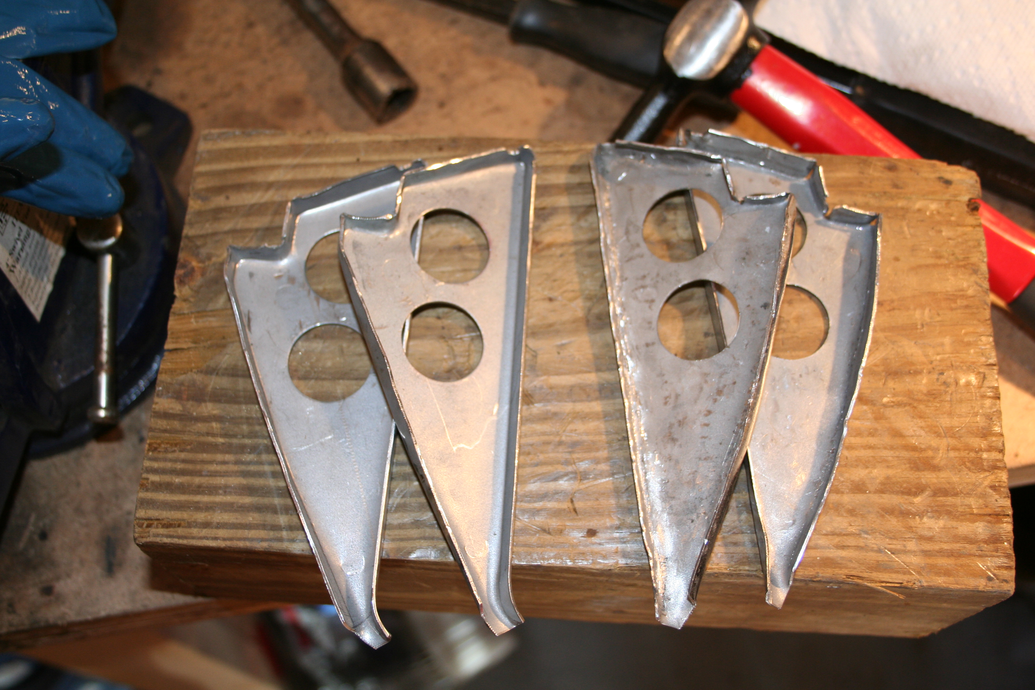
Weld into place. Rosette and seam welds need to be ground down. 5/25/2009So I had planned on purchasing new sill plates for both sides from Restoration Design... http://www.restoration-design.com I like Bill at Restoration Design. He makes some great stuff and the price is great. But, he can be very hard to get a hold of sometimes and a number of his parts are out of stock. Unfortunately he was out of the sill plates. So my only option was to purchase from Auto Atlanta... I have nothing against AA. I can't think of anyone who is more devoted to 914s than the owner George Hussey. But is body parts can be expensive. For example the sill plates are around twice what RD would charge. But AA has them in stock and RD doesn't. As it turns out the AA parts did not have the triangular sections already welded to the plates. Additionally they only provide one type of triangular sections. On the car the stamping for the driver/passenger sides are mirror images of each other. But the parts from AA match the driver side and not the passenger side. So I decided that I would flip the flange on two of the four parts so that I could great the mirror images and get the proper look for the passenger side.
The two on the left are the un modified design from AA. The two on the right are the two I modified by reversing the bends. They look a bit beat up as I had to hammer them a good bit, but when weld in place I think they will look better this way. |
|